


Page 9
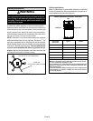
Setting Equipment
WARNING
Do not install the furnace on its front or its back. Do
not connect the return air ducts to the back of the fur-
nace. Doing so will adversely affect the operation of
the safety control devices, which could result in per-
sonal injury or death.
The ML180UHE gas furnace can be installed as shipped
in either the upflow position or the horizontal position.
Select a location that allows for the required clearances
that are listed on the unit nameplate. Also consider gas
supply connections, electrical supply, vent connection,
and installation and service clearances [24 inches (610
mm) at unit front]. The unit must be level.
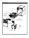
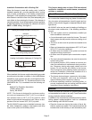
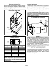
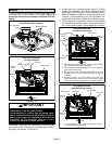
NOTE − Units with 1/2 or 3/4 hp blower motors are equipped
with three flexible legs and one rigid leg. See figure 7. The
rigid leg is equipped with a shipping bolt and a flat white
plastic washer (rather than the rubber mounting grommet
used with a flexible mounting leg). The bolt and washer
must be removed before the furnace is placed into op-
eration. After the bolt and washer have been removed, the
rigid leg will not touch the blower housing.
FIGURE 7
RIGID LEG
remove shipping bolt and washer
Units with 1/2 or 3/4 HP Blower Motor
Upflow Applications
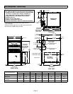
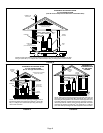
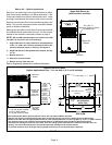
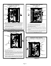
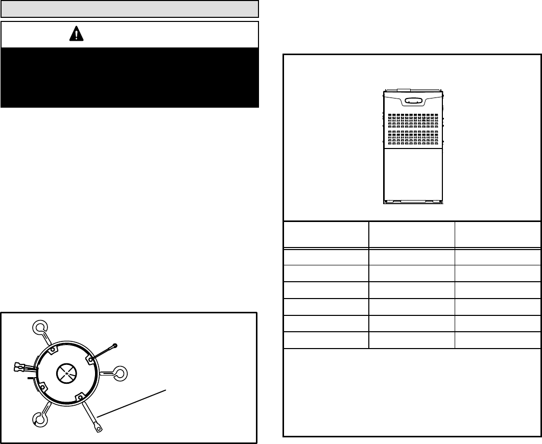
Allow for clearances to combustible materials as indicated
on the unit nameplate. Minimum clearances for closet or al-
cove installations are shown in figure 8.
Upflow Application Installation Clearances
Top
Bottom
Left Side
Right Side
Type of Vent
Connector
Type C Type B1
Top 1 in. (25 mm) 1 in. (25 mm)
*Front 2−1/4 in. (57 mm)** 2−1/4 in. (57 mm)
Back 0 0
Sides 0† 0
Vent 6 in. (152 mm) 1 in. (25 mm)
Floor 0‡ 0‡
*Front clearance in alcove installation must be 24 in. (610 mm).
Maintain a minimum of 24 in. (610 mm) for front service access.
** 4−1/2" if single wall vent pipe is used.
‡For installation on a combustible floor, do not install the furnace
directly on carpeting, tile or other combustible materials other
than wood flooring.
†Left side requires 3 inches if a single wall vent is used on 14−1/2
inch cabinets, or 2 inches if a single wall vent pipe is used on
17−1/2 inch cabinets.
FIGURE 8