


Page 13
Venting
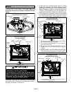
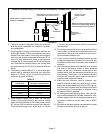
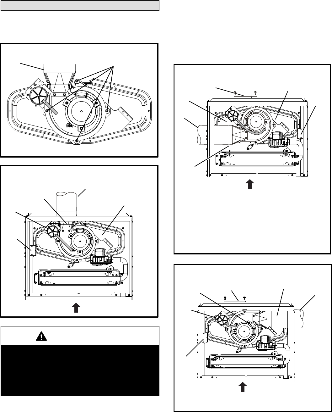
A 4−inch diameter flue transition is factory-installed on the
combustion air inducer outlet of all models. Figure 16
shows the combustion air inducer as shipped from the
factory.
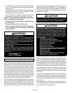
FIGURE 15
Mounting Screws Location
Mounting Screws
Flue Transition
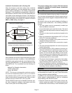
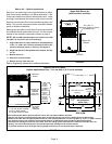
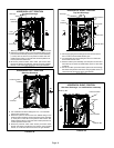
FIGURE 16
UPFLOW POSITION
Top Vent Discharge
FLOW
AIR
Collector Box
Vent Pipe
Flue
Transition
Pressure
Switch
Make−Up
Box
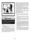
IMPORTANT
The unit will not vent properly with the flue transition
pointed down in the 6 o’clock position.
The combustion air inducer may be rotated clock-
wise or counterclockwise by 90° to allow for top or
side vent discharge in all applications. When the unit
is installed, the flue transition must be in the 9
o’clock, 12 o’clock or 3 o’clock position.
If necessary, reposition the combustion air inducer, pres-
sure switch and/or make−up box as needed per the follow-
ing steps. See figures 17 through 21.
1 − Remove the four mounting screws (figure 15) which
secure the combustion air inducer / pressure switch
assembly to the orifice plate. Lift the assembly and ro-
tate it 90 degrees clockwise or counterclockwise to ei-
ther the 3 o’clock position or to 9 o’clock position. Re−
secure with four screws. Gasket should be left in place.
2 − Use tin snips to cut preferred opening on the cabinet
for repositioning the flue outlet. Use the cut−out piece
as a cover plate to patch unused opening on cabinet.
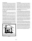
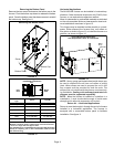
UPFLOW POSITION
Left Side Vent Discharge
FIGURE 17
D Gas supply piping must be brought into the unit from the right
side in order to accommodate the flue pipe.
D Cut Combustion air inducer tubing from 9" to 8" to avoid inter-
ference with inducer motor
D Remove make−up box assembly (2 screws) and cut wire tie to
free make−up box wires. Re−install make−up box on other side
of cabinet.
D Re−secure make−up box wires: Either pull excess wires
through the blower compartment and secure using supplied
wire tie, or coil excess wire and secure to the gas manifold.
FLOW
AIR
Make−Up
Box
Pressure
Switch
Flue
Transition
Vent Pipe
Cover Plate
Collector Box
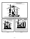
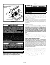
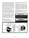
UPFLOW POSITION
Right Side Vent Discharge
FIGURE 18
FLOW
AIR
Cover Plate
Flue Transition
Vent Pipe
Pressure
Switch
Make−Up
Box
Collector Box
D Cut combustion air inducer tubing from 9" to 5" to avoid
interference with inducer motor