


Page 30
11 − Are flame rollout switches tripped? If flame rollout
switches are tripped, call the service technician for in-
spection.
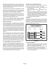
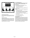
Heating Sequence Of Operation
(follow steps below or see Figure 32 for more detail)
1 − When thermostat calls for heat, combustion air blower
starts.
2 − Combustion air pressure switch proves blower opera-
tion. Switch is factory−set and requires no adjustment.
3 − After a 15−second prepurge, the hot surface ignitor en-
ergizes.
4 − After a 20−second ignitor warm−up period, the gas
valve solenoid opens. A 4−second trial for ignition peri-
od begins.
5 − Gas is ignited, flame sensor proves the flame, and the
combustion process continues.
6 − If flame is not detected after first ignition trial, the igni-
tion control will repeat steps 3 and 4 four more times
before locking out the gas valve (WATCHGUARD"
flame failure mode). The ignition control will then auto-
matically repeat steps 1 through 6 after 60 minutes.
7 − To interrupt the 60−minute WATCHGUARD" period,
move thermostat from Heat" to OFF" then back to
Heat." Heating sequence then restarts at step 1.
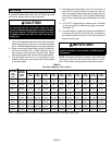
Gas Pressure Adjustment
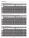
Gas Flow (Approximate)
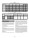
TABLE 11
GAS METER CLOCKING CHART
ML180UHE Unit
Seconds for One Revolution
Natural LP
1 cu ft
Dial
2 cu ft
Dial
1 cu ft
Dial
2 cu ft
DIAL
−045 80 160 200 400
−070 55 110 136 272
−090 41 82 102 204
−110 33 66 82 164
−135 27 54 68 136
Natural−1000 btu/cu ft LP−2500 btu/cu ft
Furnace should operate at least 5 minutes before check-
ing gas flow. Determine time in seconds for two revolu-
tions of gas through the meter. (Two revolutions assures a
more accurate time.) Divide by two and compare to time
in table 11. If manifold pressure matches table 13 and rate
is incorrect, check gas orifices for proper size and restric-
tion. Remove temporary gas meter if installed.
NOTE − To obtain accurate reading, shut off all other gas
appliances connected to meter.
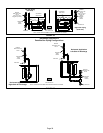
Supply Pressure Measurement
A threaded plug on the inlet side of the gas valve provides
access to the supply pressure tap. Remove the threaded
plug, install a field−provided barbed fitting and connect a
manometer to measure supply pressure. See table 13 for
proper line pressure. Replace the threaded plug after mea-
surements have been taken.
Manifold Pressure Measurement
1 − Remove the threaded plug from the outlet side of the
gas valve and install a field−provided barbed fitting.
Connect to a manometer to measure manifold pres-
sure.
2 − Start unit and allow 5 minutes for unit to reach steady
state.
3 − While waiting for the unit to stabilize, observe the
flame. Flame should be stable and should not lift from
burner. Natural gas should burn blue.
4 − After allowing unit to stabilize for 5 minutes, record
manifold pressure and compare to value given in table
13.
NOTE − Shut unit off and remove manometer as soon as an
accurate reading has been obtained. Take care to remove
barbed fitting and replace threaded plug.
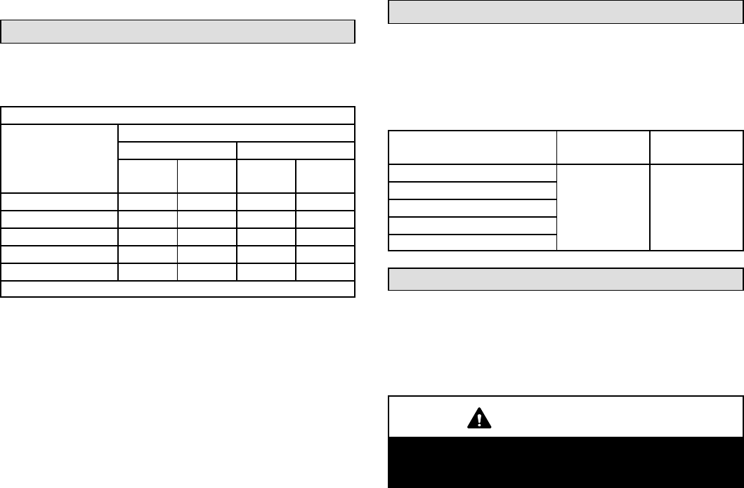
Proper Combustion
Furnace should operate a minimum 15 minutes with cor-
rect manifold pressure and gas flow rate before checking
combustion. Take combustion sample beyond the flue out-
let and compare to the tables below. The maximum car-
bon monoxide reading should not exceed 50 ppm.
TABLE 12
ML180UHE Unit
CO
2
%
For
Nat
CO
2
%
For
L.P.
−045
7.2 − 7.8 7.5 − 9.0
−070
−090
−110
−135
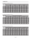
High Altitude
The manifold pressure may require adjustment and com-
bustion air pressure switch may need replacing to ensure
proper combustion at higher altitudes. Refer to table 13 for
manifold pressure and table 14 for pressure switch change
and gas conversion kits.
IMPORTANT
For safety, shut unit off and remove manometer as
soon as an accurate reading has been obtained.
Take care to replace pressure tap plug.