


Page 19
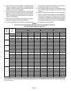
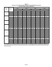
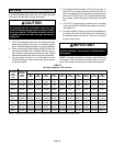
TABLE 4
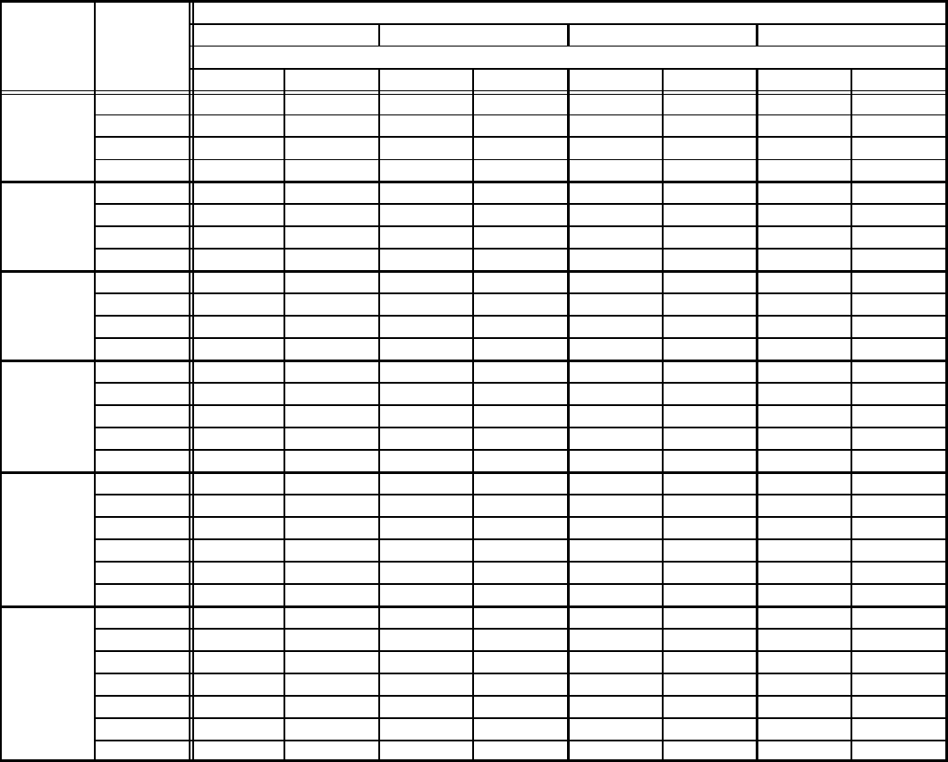
Capacity of Type B Double−Wall Vents with Single−Wall Metal Connectors
Serving a Single Category I Appliance
Height
H
(feet)
Lateral
L
(feet)
Vent and Connector Diameter − D (inches)
3 Inch 4 Inch 5 Inch 6 Inch
Appliance Input Rating in Thousands of Btu Per Hour
MIN MAX MIN MAX MIN MAX MIN MAX
6
0 38 77 59 151 85 249 126 373
2 39 51 60 96 85 156 123 231
4 NA NA 74 92 102 152 146 225
6 NA NA 83 89 114 147 163 220
8
0 37 83 58 164 83 273 123 412
2 39 56 59 108 83 176 121 261
5 NA NA 77 102 107 168 151 252
8 NA NA 90 95 122 161 175 243
10
0 37 87 57 174 82 293 120 444
2 39 61 59 117 82 193 119 287
5 52 56 76 111 105 185 148 277
10 NA NA 97 100 132 171 188 261
15
0 36 93 56 190 80 325 116 499
2 38 69 57 136 80 225 115 337
5 51 63 75 128 102 216 144 326
10 NA NA 95 116 128 201 182 308
15 NA NA NA NA 158 186 220 290
20
0 35 96 54 200 78 346 114 537
2 37 74 56 148 78 248 113 375
5 50 68 73 140 100 239 141 363
10 NA NA 93 129 125 223 177 344
15 NA NA NA NA 155 208 216 325
20 NA NA NA NA 186 192 254 306
30
0 34 99 53 211 76 372 110 584
2 37 80 55 164 76 281 109 429
5 49 74 72 157 98 271 136 417
10 NA NA 91 144 122 255 171 397
15 NA NA 115 131 151 239 208 377
20 NA NA NA NA 181 223 246 357
30 NA NA NA NA NA NA NA NA
NOTE − Single appliance venting configurations with zero lateral lengths are assumed to have no elbows in the vent system. For all other
vent configurations, the vent system is assumed to have two 90° elbows. For each additional 90° elbow or equivalent (for example two 45°
elbows equal one 90° elbow) beyond two, the maximum capacity listed in the venting table should be reduced by 10 percent (0.90 x maxi-
mum listed capacity).