


Page 31
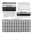
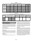
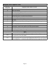
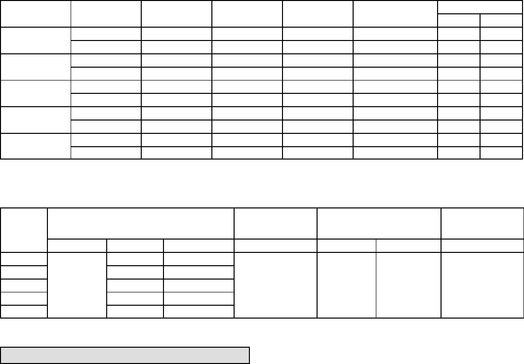
TABLE 13
Manifold Pressure Settings at all Altitudes
Model
Input Size
Gas 0−2000 ft 2001−4500 ft. 4501−7500 ft 7501 − 10,000 ft
Line Pressure in.wg.
Min Max
045
Nat 3.5 3.2 3.0 3.5 4.5 13.0
LP/propane 10.0 10.0 10.0 10.0 11.0 13.0
070
Nat 3.5 3.2 2.8 3.5 4.5 13.0
LP/propane 10.0 10.0 10.0 10.0 11.0 13.0
090
Nat 3.5 3.2 2.7 3.5 4.5 13.0
LP/propane 10.0 10 9.6 10.0 11.0 13.0
110
Nat 3.5 3.5 3.0 3.5 4.5 13.0
LP/propane 10.0 10.0 9.6 10.0 11.0 13.0
135
Nat 3.5 3.5 2.9 3.5 4.5 13.0
LP/propane 10.0 10.0 9.6 10.0 11.0 13.0
TABLE 14
Pressure Switch and Gas Conversion Kits at all Altitudes
Model
Input Size
High Altitude Pressure Switch Kit
High Altitude
Natural Gas Burner
Orifice Kit
Natural Gas to LP/Propane
Burner Orifice Kit
LP/Propane to
Natural Gas Burner
Orifice Kit
0−4500 ft 4501−7500 ft 7501 − 10,000 ft 7501 − 10,000 ft 0 − 7500 ft 7501 − 10,000 ft 0 − 7500 ft
045
No Change
80W52 80W51
73W37 70W89 76W15 73W81
070 80W52 80W51
090 80W52 80W51
110 80W57 80W52
135 80W52 80W51
NOTE − A natural to L.P. propane gas changeover kit is necessary to convert this unit. Refer to the changeover kit installation instruction for the conversion
procedure.
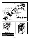
Other Unit Adjustments
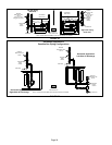
Primary and Secondary Limits
The primary limit is located on the heating compartment
vestibule panel. The secondary limits (if equipped) are lo-
cated in the blower compartment, attached to the back side
of the blower. These auto reset limits are factory−set and re-
quire no adjustment.
Flame Rollout Switches
These manually reset switches are located on the burner
box.
Pressure Switch
The pressure switch is located in the heating compartment
adjacent to the combustion air inducer. The switch checks
for proper combustion air inducer operation before allow-
ing ignition trial. The switch is factory−set and requires no
adjustment.
Temperature Rise
After the furnace has been started, and supply and return
air temperatures have been allowed to stabilize, check the
temperature rise. If necessary, adjust the blower speed to
maintain the temperature rise within the range shown on
the unit nameplate. Increase the blower speed to decrease
the temperature. Decrease the blower speed to increase
the temperature rise. Failure to adjust the temperature rise
may cause erratic limit operation.
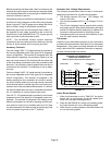
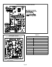
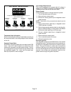
Fan Control
The heat fan−on time of 30 seconds is not adjustable. The
heat fan−off delay (amount of time that the blower operates
after the heat demand has been satisfied) may be adjusted
by changing the jumper position across the five pins on the
integrated control. The unit is shipped with a factory fan−off
delay setting of 90 seconds. The fan−off delay affects com-
fort and is adjustable to satisfy individual applications. Ad-
just the fan−off delay to achieve a supply air temperature
between 90° and 110°F at the moment that the blower is
de−energized. Longer off delay settings provide lower re-
turn air temperatures; shorter settings provide higher re-
turn air temperatures. See figure 36.