


Page 35
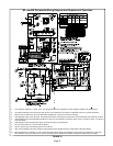
Service
WARNING
ELECTRICAL SHOCK, FIRE,
OR EXPLOSION HAZARD.
Failure to follow safety warnings exactly could result
in dangerous operation, serious injury, death or
property damage.
Improper servicing could result in dangerous opera-
tion, serious injury, death, or property damage.
Before servicing, disconnect all electrical power to
furnace.
When servicing controls, label all wires prior to dis-
connecting. Take care to reconnect wires correctly.
Verify proper operation after servicing.
At the beginning of each heating season, a qualified techni-
cian should check the system as follows:
Blower
Check the blower wheel for debris and clean if necessary.
The blower motors are prelubricated for extended bearing
life. No further lubrication is needed.
WARNING
The blower access panel must be securely in place
when the blower and burners are operating. Gas
fumes, which could contain carbon monoxide, can
be drawn into living space resulting in personal inju-
ry or death.
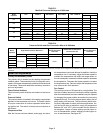
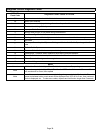
Filters
All ML180UHE filters are installed external to the unit. Fil-
ters should be inspected monthly. Clean or replace the fil-
ters when necessary to ensure that the furnace operates
properly. Replacement filters must be rated for high veloc-
ity airflow. Table 1 lists recommended filter sizes.
Flue And Chimney
1 − Check flue pipe, chimney and all connections for tight-
ness and to make sure there is no blockage.
2 − Check unit for proper draft.
Electrical
1 − Check all wiring for loose connections.
2 − Check for the correct voltage at the furnace (furnace
operating). Correct voltage is 120VAC +
10%.
3 − Check amp−draw on the blower motor with blower ac-
cess panel in place.
Unit Nameplate__________Actual__________
Cleaning the Heat Exchanger and Burners
NOTE − Use papers or protective covering in front of the fur-
nace during cleaning.
1 − Turn off both electrical and gas power supplies to fur-
nace.
2 − Remove flue pipe and top cap (some applications top
cap can remain) from the unit.
3 − Label the wires from gas valve, rollout switches, prima-
ry limit switch and make−up box then disconnect them.
4 − Remove the screws that secure the combustion air in-
ducer/pressure switch assembly to the collector box.
Carefully remove the combustion air inducer to avoid
damaging blower gasket. If gasket is damaged, it must
be replaced to prevent leakage.
5 − Remove the collector box located behind the combus-
tion air inducer. Be careful with the collector box gas-
ket. If the gasket is damaged, it must be replaced to
prevent leakage.
6 − Disconnect gas supply piping. Remove the four screws
securing the burner manifold assembly to the vestibule
panel and remove the assembly from the unit.
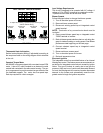
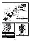
7 − NOX units only − Remove screw securing NOX insert.
Remove NOX insert. See figure 38.
8 − Remove screws from both sides, top and bottom of
vestibule panel.
9 − Remove heat exchanger. It may be necessary to
spread cabinet side to allow more room. If so, remove
five screws from the left side or right side of cabinet.
See figure 39.
10 −Backwash using steam. Begin from the burner opening
on each clam. Steam must not exceed 275°F.
11 − To clean burners, run a vacuum cleaner with a soft brush
attachment over the face of burners. Visually inspect in-
side the burners and crossovers for any blockage
caused by foreign matter. Remove any blockage. Figure
37 shows burner detail.
12 −To clean the combustion air inducer visually inspect and
using a wire brush clean where necessary. Use com-
pressed air to clean off debris and any rust.
13 −Reinstall heat exchanger in vestibule. (Replace the
five screws in the cabinet from step 10 if removed).
14 −NOx units only − Replace NOx inserts.
15 −Reinstall collector box and combustion air assembly.
Reinstall all screws to the collector box and combustion
air inducer. Failure to replace all screws may cause
leaks. Inspect gaskets for any damage and replace if
necessary.
16 −Reinstall burner box and manifold assembly.
17 −Reconnect all wires.
18 −Reconnect top cap and vent pipe to combustion air in-
ducer outlet.
19 −Reconnect gas supply piping.
20 −Turn on power and gas supply to unit.
21 −Set thermostat and check for proper operation.
22 −Check all piping connections, factory and field, for gas
leaks. Use a leak detecting solution or other preferred
means.
23 −If a leak is detected, shut gas and electricity off and
repair leak.
24 −Repeat steps 24 and 26 until no leaks are detected.
25 −Replace access panel.