


Page 12
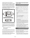
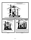
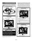
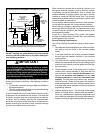
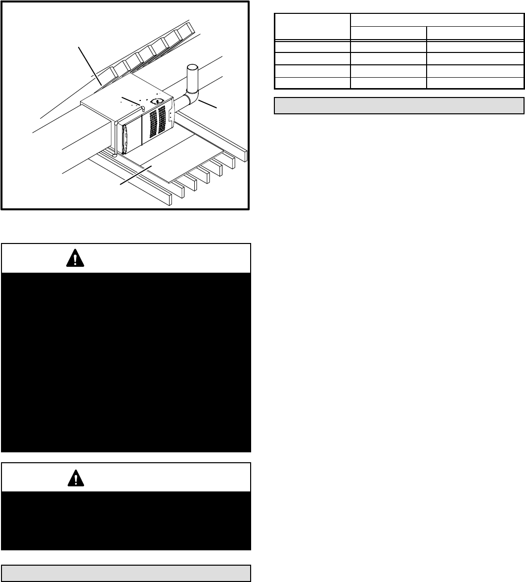
Horizontal Application
Unit Installed on Platform
FIGURE 14
clearances.
GAS
ENTRY
VENT
PIPE
See the unit nameplate for
Line contact is permissible but not preferred
SERVICE PLATFORM
WARNING
Improper installation of the furnace can result in per-
sonal injury or death. Combustion and flue products
must never be allowed to enter the return air system
or the living space. Use screws and joint tape to seal
the return air system to the furnace.
In platform installations with bottom return air, the
furnace should be sealed airtight to the return air ple-
num. A door must never be used as a portion of the
return air duct system. The base must provide a
stable support and an airtight seal to the furnace. Al-
low absolutely no sagging, cracks, gaps, etc.
The return and supply air duct systems must never
be connected to or from other heating devices such
as a fireplace or stove, etc. Fire, explosion, carbon
monoxide poisoning, personal injury and/or proper-
ty damage could result.
WARNING
The blower access panel must be securely in place
when the blower and burners are operating. Gas
fumes, which could contain carbon monoxide, can
be drawn into living space resulting in personal inju-
ry or death.
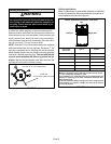
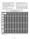
Filters
This unit is not equipped with a filter or rack. A field−pro-
vided high−velocity filter is required for the unit to operate
properly. Table 1 lists recommended filter sizes.
A filter must be in place any time the unit is operating.
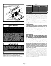
TABLE 1
Furnace
Cabinet Width
Filter Size
Side Return Bottom Return
A − 14−1/2" 16 X 25 X 1 (1) 14 X 25 X 1 (1)
B − 17−1/2" 16 X 25 X 1 (1) 16 X 25 X 1 (1)
C − 21" 16 X 25 X 1 (1) 20 X 25 X 1 (1)
D − 24−1/2" 16 X 25 X 1 (2) 24 X 25 X 1 (1)
Duct System
Use industry-approved standards (such as those pub-
lished by Air Conditioning Contractors of America or Ameri-
can Society of Heating, Refrigerating and Air Conditioning
Engineers) to size and install the supply and return air duct
system. This will result in a quiet and low-static system that
has uniform air distribution.
NOTE − Do not operate the furnace in the heating mode
with an external static pressure that exceeds 0.5 inches
w.c. Higher external static pressures may cause erratic lim-
it operation.
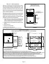
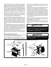
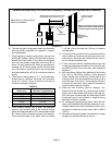
Supply Air Plenum
If the furnace is installed without a cooling coil, a removable
access panel must be installed in the supply air duct. The
access panel should be large enough to permit inspection
(either by smoke or reflected light) of the heat exchanger
for leaks after the furnace is installed. The furnace access
panel must always be in place when the furnace is operat-
ing and it must not allow leaks into the supply air duct sys-
tem.
Return Air Plenum
NOTE − Return air must not be drawn from a room-
where this furnace, or any other gas−fueled appliance
(i.e., water heater), or carbon monoxide producing de-
vice (i.e., wood fireplace) is installed.
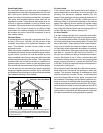
When return air is drawn from a room, a negative pres-
sure is created in the room. If a gas appliance is operating
in a room with negative pressure, the flue products can
be pulled back down the vent pipe and into the room. This
reverse flow of the flue gas may result in incomplete com-
bustion and the formation of carbon monoxide gas. This
toxic gas might then be distributed throughout the house
by the furnace duct system.
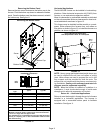
In upflow applications, the return air can be brought in
through the bottom or either side of the furnace. If a fur-
nace with bottom return air is installed on a platform, make
an airtight seal between the bottom of the furnace and the
platform to ensure that the unit operates properly and
safely. Use fiberglass sealing strips, caulking, or equiva-
lent sealing method between the plenum and the furnace
cabinet to ensure a tight seal. If a filter is installed, size the
return air duct to fit the filter frame.