


Page 27
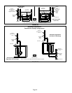
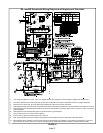
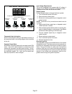
1 − Line voltage is applied to L1 and N. the T1 low voltage transformer is energized, and line voltage is applied to B3 indoor blower.
2 − S47 rollout switch(es) must be closed in order for 24V from transformer to be output on integrated control "R" to power thermostat.
3 − When there is a call for heat, W1 of the thermostat energizes W of the furnace control with 24VAC.
4 − A92 integrated control runs a self−check. S10 primary limit and S21 secondary limit contacts are found to be closed. Call for heat can continue.
5 − A92 integrated control energizes B6 combustion air inducer. S18 combustion air pressure switch closes . Once S18 closes, a 15−second
pre−purge follows.
6 − A92 integrated control energizes R33 ignitor. A 20−second warm−up period begins.
7 − GV1 gas valve opens for a 4−second trial for ignition
8 − Flame is sensed, gas valve remains open for the heat call.
9 − After 30−second delay (from flame sensed), A92 integrated control applies 24vVAC to Heat speed of B3 indoor blower.
10 − When heat demand is satisfied, W1 of the indoor thermostat de−energizes W of A92ignition control which de−energizes GV1 gas valve.
B6 combustion air inducer continues a 5−second post−purge period, and B3 indoor blower completes a selected OFF time delay.
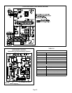
FIGURE 32
ML180UHE Schematic Wiring Diagram and Sequence of Operation
1
8
2
4
5
6
7
3
9
10
1
5