


Page 17
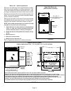
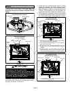
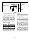
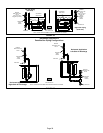
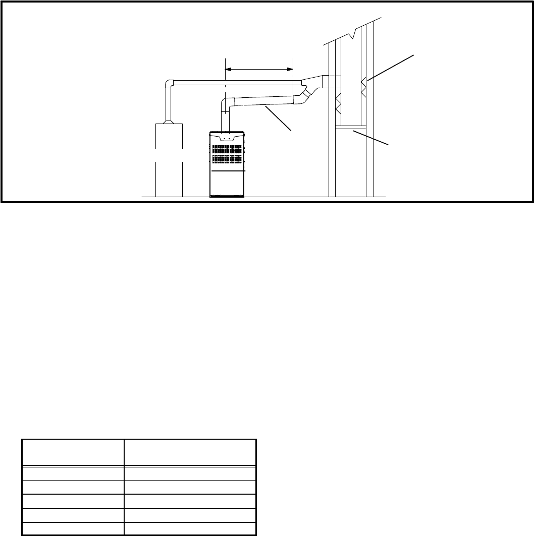
FIGURE 25
Common Venting Using Tile−Lined Interior Masonry Chimney and Combined Vent Connector
MINIMUM LENGTH = AS SHORT AS PRACTICAL.
FOR MAXIMUM LENGTH SEE NOTE TO LEFT
INTERIOR TILE−LINED
MASONRY CHIMNEY
NOTE − the chimney must be properly
sized per provided venting tables or
lined with listed metal lining system.
PERMANENTLY
SEALED FIREPLACE
OPENING
VENT
CONNECTOR
NOTE− Refer to provided venting
tables for installations.
FURNACE
OTHER
APPLIANCE
6 − The entire length of single wall metal vent connector
shall be readily accessible for inspection, cleaning,
and replacement.
7 − Single appliance venting configurations with zero lat-
eral lengths (tables 3 and 4) are assumed to have no
elbows in the vent system. For all other vent configura-
tions, the vent system is assumed to have two 90° el-
bows. For each additional 90° elbow or equivalent (for
example two 45° elbows equal one 90° elbow) beyond
two, the maximum capacity listed in the venting table
should be reduced by 10% (0.90 x maximum listed ca-
pacity).
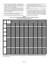
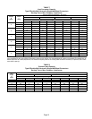
8 − The common venting tables (5, 6, 7, and 8) were gen-
erated using a maximum horizontal vent connector
length of 1−1/2 feet (.46 m) for each inch (25 mm) of
connector diameter as follows:
TABLE 2
Connector Diameter
inches (mm)
Maximum Horizontal
Connector Length feet (m)
3 (76) 4−1/2 (1.37)
4 (102) 6 (1.83)
5 (127) 7−1/2 (2.29)
6 (152) 9 (2.74)
7 (178) 10−1/2 (3.20)
9 − If the common vertical vent is offset, the maximum
common vent capacity listed in the common venting
tables should be reduced by 20%, the equivalent of two
90° elbows (0.80 x maximum common vent capacity).
The horizontal length of the offset shall not exceed
1-1/2 feet (.46 m) for each inch (25 mm) of common
vent diameter.
10 − The vent pipe should be as short as possible with the
least number of elbows and angles required to com-
plete the job. Route the vent connector to the vent us-
ing the shortest possible route.
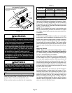
11 − A vent connector shall be supported without any dips
or sags and shall slope a minimum of 1/4 inch (6.4 mm)
per linear foot (305 mm) of connector, back toward the
appliance.
12 − Vent connectors shall be firmly attached to the furnace
flue collar by self−drilling screws or other approved
means, except vent connectors of listed type B vent
material which shall be assembled according to the
manufacturer’s instructions. Joints between sections
of single wall connector piping shall be fastened by
screws or other approved means.
13 − When the vent connector used for Category I ap-
pliances must be located in or pass through a crawl-
space, attic or other areas which may be cold, that por-
tion of the vent connector shall be constructed of listed
double-wall type B vent material or material having
equivalent insulation qualities.
14 − All venting pipe passing through floors, walls, and ceil-
ings must be installed with the listed clearance to com-
bustible materials and be fire stopped according to lo-
cal codes. In absence of local codes, refer to NFGC
(Z223.1).
15 − No portion of the venting system can extend into, or pass
through any circulation air duct or plenum.