


Page 23
Gas Piping
Gas supply piping should not allow more than 0.5"W.C. drop
in pressure between gas meter and unit. Supply gas pipe
must not be smaller than unit gas connection.
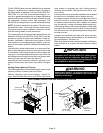
CAUTION
If a flexible gas connector is required or allowed by
the authority that has jurisdiction, black iron pipe
shall be installed at the gas valve and extend outside
the furnace cabinet. The flexible connector can then
be added between the black iron pipe and the gas
supply line.
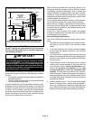
Gas Supply
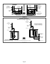
1 − This unit is shipped standard for left or right side instal-
lation of gas piping (or top entry in horizontal applica-
tions). Connect the gas supply to the piping assembly.
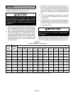
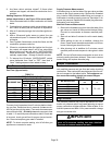
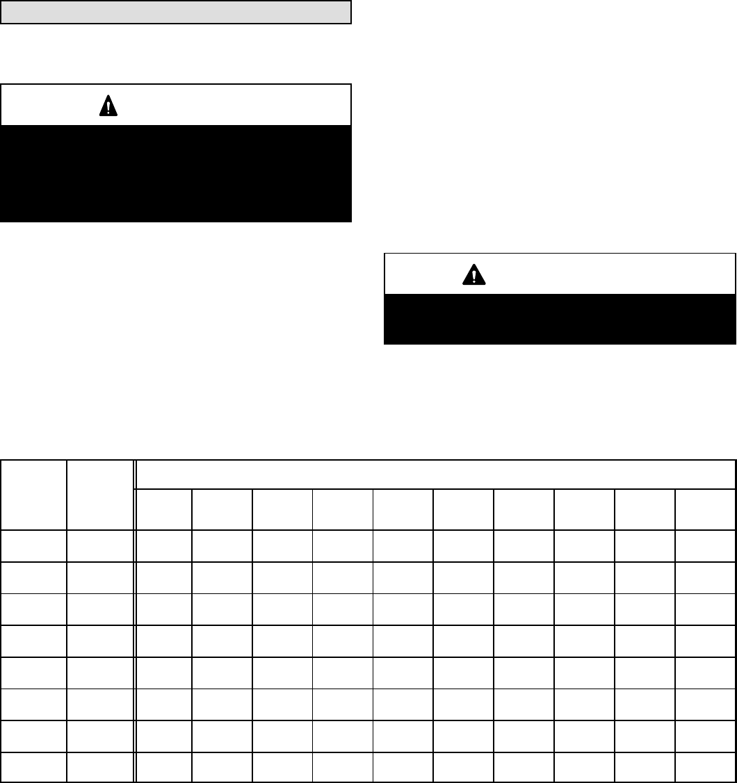
2 − When connecting the gas supply piping, consider fac-
tors such as length of run, number of fittings, and fur-
nace rating to avoid excessive pressure drop. Table 9
lists recommended pipe sizes for typical applications.
3 − The gas piping must not run in or through air ducts,
clothes chutes, gas vents or chimneys, dumb waiters,
or elevator shafts.
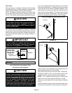
4 − The piping should be sloped 1/4 inch (6.4 mm) per 15
feet (4.57 m) upward toward the meter from the fur-
nace. The piping must be supported at proper intervals
[every 8 to 10 feet (2.44 to 3.01 m)] with suitable hang-
ers or straps. Install a drip leg in vertical pipe runs to the
unit.
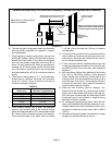
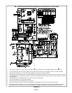
5 − A 1/8" N.P.T. plugged tap or pressure post is located
on the gas valve to facilitate test gauge connection.
See figure 35.
6 − In some localities, codes may require the installation of
a manual main shut-off valve and union (furnished by
the installer) external to the unit. The union must be of
the ground joint type.
IMPORTANT
Compounds used on threaded joints of gas piping
must be resistant to the actions of liquified petro-
leum gases.
NOTE − If emergency shutoff is necessary, shut off the main
manual gas valve and disconnect main power to the fur-
nace. The installer should properly label these devices.
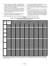
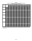
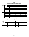
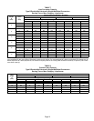
TABLE 9
Gas Pipe Capacity − ft
3
/hr (m
3
/hr)
Nominal
Iron Pipe
Size
inches
(mm)
Internal
Diameter
inches
(mm)
Length of Pipe − feet (m)
10
(3.048)
20
(6.096)
30
(9.144)
40
(12.192)
50
(15.240)
60
(18.288)
70
(21.336)
80
(24.384)
90
(27.432)
100
(30.480)
1/2
(12.7)
.622
(17.799)
172
(4.87)
118
(3.34)
95
(2.69)
81
(2.29)
72
(2.03)
65
(1.84)
60
(1.69)
56
(1.58)
52
(1.47)
50
(1.42)
3/4
(19.05)
.824
(20.930)
360
(10.19)
247
(7.00)
199
(5.63)
170
(4.81)
151
(4.28)
137
(3.87)
126
(3.56)
117
(3.31)
110
(3.11)
104
(2.94)
1
(25.4)
1.049
(26.645)
678
(19.19)
466
(13.19)
374
(10.59)
320
(9.06)
284
(8.04)
257
(7.27)
237
(6.71)
220
(6.23)
207
(5.86)
195
(5.52)
1−1/4
(31.75)
1.380
(35.052)
1350
(38.22)
957
(27.09)
768
(22.25)
657
(18.60)
583
(16.50)
528
(14.95)
486
(13.76)
452
(12.79)
424
(12.00)
400
(11.33)
1−1/2
(38.1)
1.610
(40.894)
2090
(59.18)
1430
(40.49)
1150
(32.56)
985
(27.89)
873
(24.72)
791
(22.39)
728
(20.61)
677
(19.17)
635
(17.98)
600
(17.00)
2
(50.8)
2.067
(52.502)
4020
(113.83)
2760
(78.15)
2220
(62.86)
1900
(53.80)
1680
(47.57)
1520
(43.04)
1400
(39.64)
1300
(36.81)
1220
(34.55)
1160
(32.844)
2−1/2
(63.5)
2.469
(67.713)
6400
(181.22)
4400
(124.59)
3530
(99.95)
3020
(85.51)
2680
(75.88)
2480
(70.22)
2230
(63.14)
2080
(58.89)
1950
(55.22)
1840
(52.10)
3
(76.2)
3.068
(77.927)
11300
(319.98)
7780
(220.30)
6250
(176.98)
5350
(151.49)
4740
(134.22)
4290
(121.47)
3950
(111.85)
3670
(103.92)
3450
(97.69)
3260
(92.31)
NOTE − Capacity given in cubic feet (m
3
) of gas per hour and based on 0.60 specific gravity gas.