Page 18
16 − Vent connectors serving Category I appliances shall
not be connected to any portion of mechanical draft
systems operating under positive pressure such as
Category III or IV venting systems.
17 − If vent connectors are combined prior to entering the
common vent, the maximum common vent capacity
listed in the common venting tables must be reduced by
10%, the equivalent of one 90° elbow (0.90 x maximum
common vent capacity).
18 − The common vent diameter must always be at least as
large as the largest vent connector diameter.
19 − In no case, shall the vent connector be sized more than
two consecutive table size diameters over the size of
the draft hood outlet or flue collar outlet.
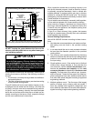
20 − Do not install a manual damper, barometric draft regu-
lator or flue restrictor between the furnace and the
chimney.
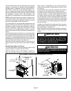
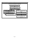
21 − When connecting this appliance to an existing dedi-
cated or common venting system, you must inspect the
venting system’s general condition and look for signs
of corrosion. The existing vent pipe size must conform
to these instructions and the provided venting tables. If
the existing venting system does not meet these re-
quirements, it must be resized.
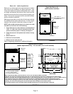
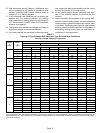
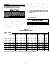
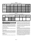
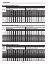
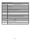
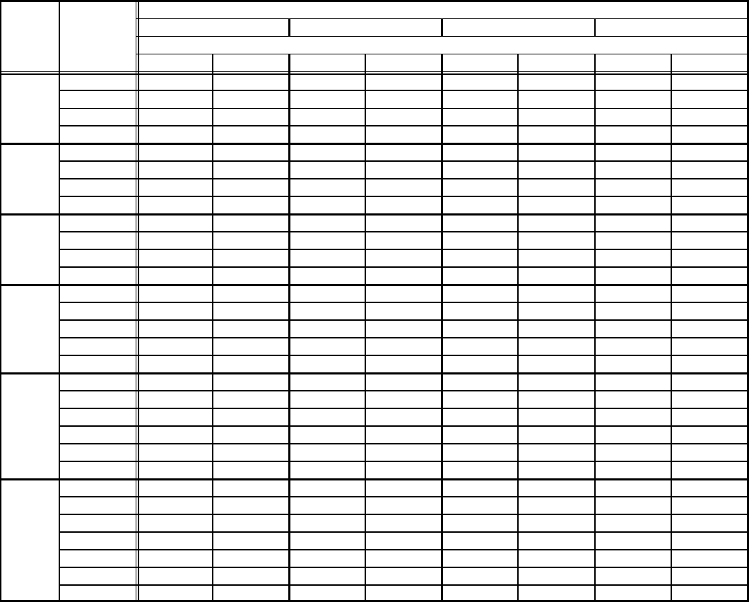
TABLE 3
Capacity of Type B Double−Wall Vents with Type B Double−Wall Connectors
Serving a Single Category I Appliance
Height
H
(feet)
Lateral
L
(feet)
Vent and Connector Diameter − D (inches)
3 Inch 4 Inch 5 Inch 6 Inch
Appliance Input Rating in Thousands of Btu Per Hour
MIN MAX MIN MAX MIN MAX MIN MAX
6
0 0 78 0 152 0 251 0 375
2 13 51 18 97 27 157 32 232
4 21 49 30 94 39 153 50 227
6 25 46 36 91 47 149 59 223
8
0 0 84 0 165 0 276 0 415
2 12 57 16 109 25 178 28 263
5 23 53 32 103 42 171 53 255
8 28 49 39 98 51 164 64 247
10
0 0 88 0 175 0 295 0 447
2 12 61 17 118 23 194 26 289
5 23 57 32 113 41 187 52 280
10 30 51 41 104 54 176 67 267
15
0 0 94 0 191 0 327 0 502
2 11 69 15 136 20 226 22 339
5 22 65 30 130 39 219 49 330
10 29 59 40 121 51 206 64 315
15 35 53 48 112 61 195 76 301
20
0 0 97 0 202 0 349 0 540
2 10 75 14 149 18 250 20 377
5 21 71 29 143 38 242 47 367
10 28 64 38 133 50 229 62 351
15 34 58 46 124 59 217 73 337
20 48 52 55 116 69 206 84 322
30
0 0 100 0 213 0 374 0 587
2 9 81 13 166 14 283 18 432
5 21 77 28 160 36 275 45 421
10 27 70 37 150 48 262 59 405
15 33 64 44 141 57 249 70 389
20 56 58 53 132 66 237 80 374
30 NA NA 73 113 88 214 104 346
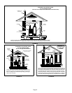
NOTE − Single appliance venting configurations with zero lateral lengths are assumed to have no elbows in the vent system. For all other
vent configurations, the vent system is assumed to have two 90° elbows. For each additional 90° elbow or equivalent (for example two 45°
elbows equal one 90° elbow) beyond two, the maximum capacity listed in the venting table should be reduced by 10 percent (0.90 x maxi-
mum listed capacity).