


Page 25
Leak Check
After gas piping is completed, carefully check all piping
connections (factory− and field−installed) for gas leaks. Use
a leak detecting solution or other preferred means.
NOTE − If emergency shutoff is necessary, shut off the main
manual gas valve and disconnect the main power to the
furnace. The installer should properly label these devices.
CAUTION
Some soaps used for leak detection are corrosive to
certain metals. Carefully rinse piping thoroughly af-
ter leak test has been completed. Do not use
matches, candles, flame or other sources of ignition
to check for gas leaks.
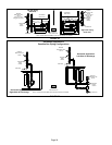
The furnace must be isolated by closing its individual
manual shut-off valve and disconnecting from from the gas
supply system during any pressure testing of the gas sup-
ply system at pressures greater than 1/2 psig (3.48 kPa, 14
inches w.c.).
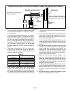
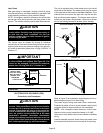
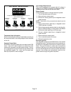
IMPORTANT
When testing pressure of gas lines, gas valve must
be disconnected and isolated. See figure 28. Gas
valves can be damaged if subjected to pressures
greater than 1/2 psig (3.48 kPa, 14 inches w.c.).
MANUAL MAIN
SHUT−OFF VALVE
WILL NOT HOLD
NORMAL TEST
PRESSURE
CAP
ISOLATE
GAS VALVE
FURNACE
FIGURE 28
1/8 NPT PLUG
Electrical
ELECTROSTATIC DISCHARGE (ESD)
Precautions and Procedures
CAUTION
Electrostatic discharge can affect electronic com-
ponents. Take precautions during furnace installa-
tion and service to protect the furnace’s electronic
controls. Precautions will help to avoid control ex-
posure to electrostatic discharge by putting the fur-
nace, the control and the technician at the same
electrostatic potential. Neutralize electrostatic
charge by touching hand and all tools on an un-
painted unit surface, such as the gas valve or blower
deck, before performing any service procedure.
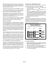
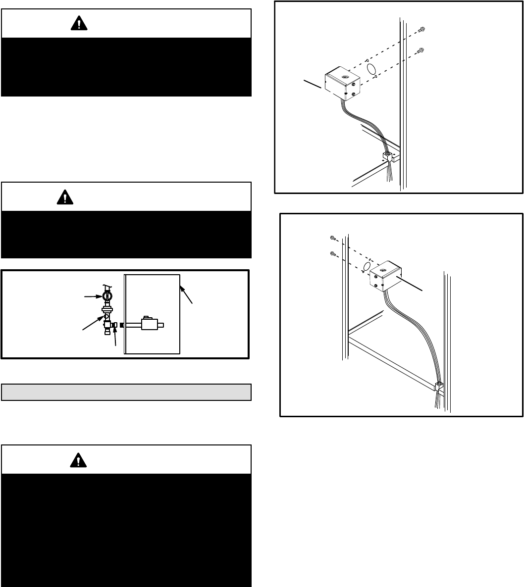
The unit is equipped with a field make−up box on the left
hand side of the cabinet. The make−up box may be moved
to the right side of the furnace to facilitate installation. If the
make−up box is moved to the right side, clip the wire ties
that bundle the wires together. The excess wire must be
pulled into the blower compartment. Secure the excess
wire to the existing harness to protect it from damage.
INTERIOR MAKE−UP BOX INSTALLATION
FIGURE 29
BOX
Right Side
INTERIOR MAKE−UP BOX INSTALLATION
FIGURE 30
BOX
Left side
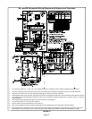
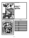
Refer to figure 32 for schematic wiring diagram and trou-
bleshooting and figure 33 for field wiring.
The power supply wiring must meet Class I restrictions.
Protected by either a fuse or circuit breaker, select circuit
protection and wire size according to unit nameplate.
NOTE − Unit nameplate states maximum current draw.
Maximum over−current protection allowed is 15 AMP.
Holes are on both sides of the furnace cabinet to facilitate
wiring.
Install a separate (properly sized) disconnect switch near
the furnace so that power can be turned off for servicing.