


Page 7
XP17 SERIES
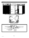
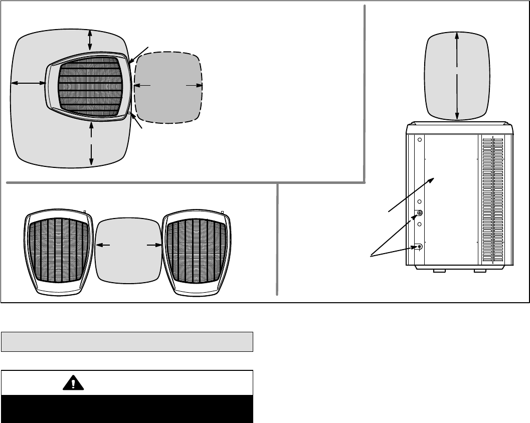
CONTROL PANEL
ACCESS
LOCATION
6 (152)
36 (914)
12 (305)
30 (762)
LINE SET
CONNECTIONS
24 (610)
LINE SET
CONNECTIONS
ACCESS PANEL
REAR VIEW OF UNIT
48 (1219)
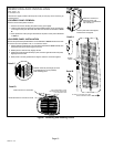
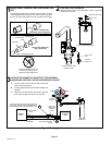
MINIMUM CLEARANCE BETWEEN
TWO UNITS
CLEARANCE ON ALL SIDES Ċ INCHES (MILLIMETERS)
ACCESS PANEL
MINIMUM CLEARANCE
ABOVE UNIT
NOTES:
S CLEARANCE TO ONE OF THE
OTHER THREE SIDES MUST BE 36
INCHES (914MM).
S CLEARANCE TO ONE OF THE
REMAINING TWO SIDES MAY BE 12
INCHES (305MM) AND THE FINAL
SIDE MAY BE 6 INCHES (152MM).
Figure 4. Installation Clearances
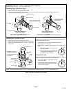
Unit Placement
CAUTION
In order to avoid injury, take proper precaution when lift-
ing heavy objects.
See Unit Dimensions on page 3 for sizing mounting slab,
platforms or supports. Refer to figure 4 for mandatory
installation clearance requirements.
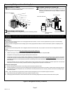
POSITIONING CONSIDERATIONS
Consider the following when positioning the unit:
S Some localities are adopting sound ordinances based
on the unit’s sound level registered from the adjacent
property, not from the installation property. Install the
unit as far as possible from the property line.
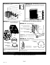
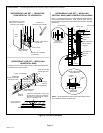
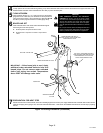
S When possible, do not install the unit directly outside
a window. Glass has a very high level of sound
transmission. For proper placement of unit in relation
to a window see the provided illustration in figure 5,
detail A.
PLACING UNIT ON SLAB
When installing unit at grade level, the top of the slab
should be high enough above grade so that water from
higher ground will not collect around the unit. The slab
should have a slope tolerance as described in figure 5,
detail B.
NOTE Ċ If necessary for stability, anchor unit to slab as
described in figure 5, detail D.
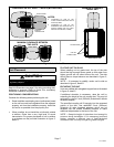
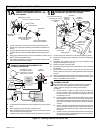
ELEVATING THE UNIT
Units are outfitted with elongated support feet as illustrated
in figure 5, detail C.
If additional elevation is necessary, raise the unit by
extending the height of the unit support feet. This may be
achieved by using a 2 inch (50.8mm) Schedule 40 female
threaded adapter.
The specified coupling will fit snuggly into the recessed
portion of the feet. Use additional 2−inch (50.8mm)
Schedule 40 male threaded adaptors which can be
threaded into the female threaded adaptors to make
additional adjustments to the level of the unit.
NOTE Ċ Keep the height of extenders short enough to
ensure a sturdy installation. If it is necessary to extend
further, consider a different type of field−fabricated
framework that is sturdy enough for greater heights.