


Page 24
506586−01 10/10
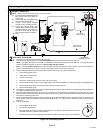
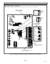
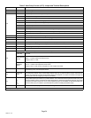
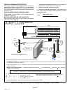
Table 3. Heat Pump Control (A175) Jumper and Terminal Descriptions
Board ID Label Description
E12 PSC Fan 240 VAC output connection for outdoor fan.
E16 PSC Fan 240 VAC input connection for outdoor fan.
E18
W 24VAC output for defrost auxiliary heat output.
L Thermostat service light connection.
Y2 24VAC thermostat input/output for second stage operation of the unit.
Y1 24VAC thermostat input for first stage operation of the unit.
O 24VAC thermostat input for reversing valve operation
DS Humiditrol Input
C 24VAC system common
i− Input/Output − RSBus data low. Used in communicating mode only with compatible indoor thermostat.
i+ Input/Output − RSBus data high. Used in communicating mode only with compatible indoor thermostat.
R 24VAC system power input
E19 and E20 O OUT 24 VAC output connection for reversing valve.
E21 and E22 LO−PS Connection for low−pressure switch (2.4 milliamps @ 18VAC)
E31 and E32 Y1 OUT 24 VAC common output, switched for enabling compressor contactor.
E24 and E25 HS−PS S87 connection for high−pressure switch (E25) and 24VAC (E24) to A177 R" input.
E26 FAN 1 First Stage and second stage basic and precision dehumidification ECM fan motor 24VDC output connection 1.
E27 FAN 2 Second stage basic and precision dehumidification ECM fan motor 24VDC output connection 2.
E28 FAN C ECM common connection for ECM fan.
E30
Six position square pin header. P4 provides connections for the temperature sensors.
DIS
(YELLOW)
Not used.
AMB (BLACK)
(RT13)
AMB 1 Ċ Outdoor ambient temperature sensor supply.
AMB 2 Ċ Outdoor ambient temperature return.
Range is −40ºF to +140ºF
COIL
(BROWN)
(RT21)
COIL 1 Ċ Outdoor coil temperature sensor supply.
COIL 2 Ċ Outdoor coil temperature sensor return
Range is −40ºF to 140ºF. Sensor is clipped on a 5/16" copper return bend.
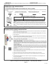
E33 Field Test
This jumper allows service personnel to defeat the timed off control, initiate or terminate a defrost and field
programming of unit nominal capacity feature.
E37
Comp Shift
Delay
Two position square pin header. When jumper is installed, a 30−second compressor shift delay which de−energizes
the compressor contactor output, second−stage solenoid output (if on) and the ECM fan outputs. After the timer
expires, the compressor contactor and ECM fan outputs are energized. If no jumper is installed, it changes the
reversing valve with de−energizing the outputs immediately.
E47
50*
70
90
100
Seven position square pin header. E47 provides selection of the defrost terminate temperature based on the posi-
tion of the selection jumper. The defrost termination temperature is measured by the defrost coil sensor. The jumper
termination pin is factory set at 50°F (10°C). If the temperature jumper is not installed, the default termination tem-
perature is 90°F (32°C). In addition, it provides selection points for enabling the field test mode.
W1 Short DS To R Cut for Humiditrol (EDA) application. Use only in two−stage units.
* Factory default setting