


Page 33
XP17 SERIES
UNIT SENSORS
Sensors connect to the heat pump control through a
field-replaceable harness assembly that plugs into the
control. Through the sensors, the heat pump control
detects outdoor ambient and coil temperature fault
conditions. As the detected temperature changes, the
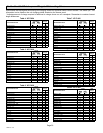
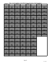
resistance across the sensor changes. table 13 shows
how the resistance varies as the temperature changes for
both type of sensors. Sensor resistance values can be
checked by ohming across pins shown in table 12.
NOTE Ċ When checking the ohms across a sensor, be
aware that a sensor showing a resistance value that is not
within the range shown in table 12, may be performing as
designed. However, if a shorted or open circuit is detected,
then the sensor may be faulty and the sensor harness will
need to be replaced.
Ambient Temperature Sensor (RT13)
See table 12 for sensor range. If the ambient sensor is
detected as being open, shorted or out of the temperature
range of the sensor, the heat pump control will not perform
demand defrost operation. The heat pump control will
revert to time/temperature defrost operation and will
display the appropriate alert code. Heating and cooling
operation will be allowed in this fault condition.
Coil Temperature Sensor (RT21)
See table 12 for sensor range. If the defrost coil sensor is
open, shorted or out of the temperature range of the
sensor, the heat pump control will not perform demand or
time/temperature defrost operation and will display the
appropriate fault code. Heating and cooling operation will
be allowed in this fault condition.
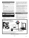
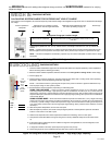
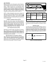
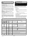
High Discharge Line Temperature Sensor
This model does not use a high discharge line temperature
sensor. The cable assembly attached to the heat pump
control’s E30 connection has a 10K resister installed
between pins 1 and 2 as illustrated in figure 24. No alerts or
alarms would be generated if resistor is damage.
10K RESISTOR
AMBIENT AIR
TEMPERATURE SENSOR
COIL TEMPERATURE
SENSOR
Figure 24. 10k Resistor Location
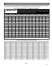
Table 12. Sensor Temperature / Resistance Range
Sensor
Temperature
Range °F (°C)
Resistance values
range (ohms)
Pins/Wire
Color
Outdoor
(Ambient)
−40 (−40) to 140
(60)
280,000 to 3750
3 and 4
(Black)
Coil
5 and 6
(Brown)
NOTE Ċ Sensor resistance decreases as sensed temperature
increases (see table 13).
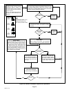
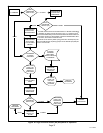
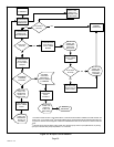
W Input Fault or Miswire
In case of a W input fault or possible miswire, the system
will function as listed in the sequence of operation in figure
30.
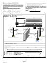
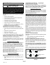
Shift Delay (E37)
The heat pump control has a field−selectable function to
reduce occasional sounds that may occur while the unit is
cycling in and out of the defrost mode. When a jumper is
installed on the DELAY pins (E37), the compressor will be
cycled off for 30 seconds going in and out of the defrost
mode. Units are shipped with jumper installed on DELAY
pins.
FACTORY DEFAULT OR WHEN
JUMPER IS MISSING
30
0
*30
SECOND DELAY
SECOND DELAY
0
Figure 25. Shift Delay Settings