


Page 41
XP17 SERIES
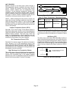
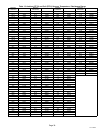
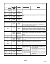
System fault and lockout LED (DS11 / DS14) alarm codes takes precedence over system status LED codes (cooling, heating stages or
defrost/dehumidification). Only the latest active LED fault or lockout alarm code if present will be displayed. If no fault or lockout codes are active, then
system status LEDs are routinely displayed. See notes 1 and 2 in table below for duration of fast / slow flashes and pause.
Heat Pump Control
LEDs
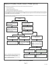
SolutionPossible Cause(s)Condition
icomfort
Touch
®
Thermostat
Display
DS11
Green
SolutionPossible Cause(s)Condition
icomfort
Touch
®
Thermostat
Display
DS14 Red
DS11
Green
SolutionPossible Cause(s)Condition
icomfort
Touch
®
Thermostat
Display
DS14 Red
Off
1 fast flash
then pause
Not
applicable
Single stage
compressor
heating
These are codes that show status of operation whether the system is operating in either
in first or second stage heating or cooling operation, defrost or in the dehumidification
modes.
On
2 fast
flashes
then pause
Not
applicable
Defrost
1 fast flash
then pause
Off
Not
applicable
Single−stage
compressor
cooling
2 fast
flashes
then pause
On
Not
applicable
Dehumidification
mode
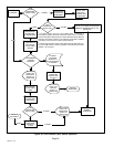
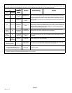
ALERT STATUS
None
Moderate
Alert Code
105
Device
communication
failure
icomfort Touch
®
thermostat is unable to communicate with any other device on the
RSBus. Alarm only occurs if a specific device did communicate initially after power
up and communication was later lost. Possible causes are lost connection, bus
short or open, or other device stop responding.
None
Moderate
Alert Code
120
Unresponsive
device
Message could be sent by any device on RSBus if expected response message is
not received from other device. If sent by indoor or heat pump control, device did
not get expected response (incorrect or no response at all) from active Subnet
controller. If sent by the icomfort Touch
®
thermostat, and did not get the expected
response (incorrect or no response at all) from device. Normally this indicate device
malfunction.
None
Critical Alert
Code 124
Active subnet
controller missing
Device lost connection to icomfort Touch
®
thermostat. Thermostat is sending
heartbeat message in one minute intervals. Device sets this alarm if no Heartbeat is
received for three minutes. Normally this indicate lost connection to thermostat, or
thermostat is not working. Alert will clear after valid subnet controller message is
received.
None
Critical Alert
Code 125
Hardware Failure
Entire or partial system failure. Alert will clear 300 seconds after fault has
recovered.
None
Moderate /
Critical Alert
Code 126
Internal control
communication
failure
Internal communication on heat pump control. Alert will clear 300 seconds after fault
has recovered.
None
Critical Alert
Code 131
Corrupted control
parameters
System stored configuration data is corrupted. System will not run.
None
Critical Alert
Code 132
Failed flash CRC
check.
No operations, heat pump control enters boot loader mode. Alarm will clears after
reset. Refer to communicating thermostat for memory corrupt handling.
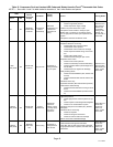
Off
Slow flash
Moderate
Alert Code
410
Low pressure
fault
1
Restricted air flow over in-
door or outdoor coil.
2
Improper refrigerant
charge in system.
3
Improper metering device
installed or incorrect op-
eration of metering device.
4
Incorrect or improper sen-
sor location or connection
to system.
1
Remove any blockages or restrictions from coils
and/or fans. Check indoor and outdoor fan motor
for proper current draws.
2
Check system charge using approach and sub-
cooling temperatures.
3
Check system operating pressures and compare
to unit charging charts.
4
Make sure all pressure switches and sensors have
secure connections to system to prevent refriger-
ant leaks or errors in pressure and temperature
measurements.
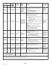
Off On
Critical Alert
Code 411
Low pressure
switch lockout
Slow flash Off
Moderate
Alert Code
412
High pressure
fault
On Off
Critical Alert
Code 413
High pressure
switch lockout