


Page 21
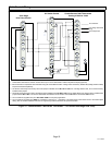
XP17 SERIES
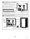
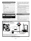
NOTE Ċ For proper voltages, select control wires gauge per table below.
WIRE RUN LENGTH AWG# INSULATION TYPE
LESS THAN 100’ (30 METERS) 18 TEMPERATURE RATING
MORE THAN 100’ (30 METERS) 16 35ºC MINIMUM.
NOTE Ċ Wire tie provides low voltage wire strain relief and to maintain
separation of field installed low and high voltage circuits.
NOTE Ċ Do not bundle any excess 24VAC control wires inside control box.
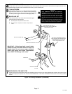
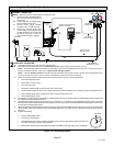
A. ROUTE CONTROL WIRES Ċ NON−COMMUNICATING
A
B
HEAT PUMP
CONTROL (A175)
CONTROL BOX
HOLE
Install low voltage control wiring from outdoor to indoor unit and from
thermostat to indoor unit.
3
A Run 24VAC control wires through hole with grommet.
B Make 24VAC control wire connections to heat pump control (A175) .
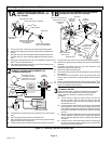
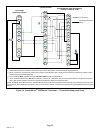
B. ROUTE CONTROL WIRES Ċ COMMUNICATING
Maximum length of wiring (18 gauge) for all connections on the RSBus is limited to 1500 feet (457 meters). Color−coded, temperature rating 95
º
F (35
º
C)
minimum, solid core. (Class II Rated Wiring)
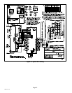
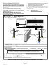
Any excess high voltage field wiring should be trimmed and secured away from any low voltage field wiring. To facilitate a conduit, a
cutout is located in the bottom of the control box. Connect conduit to the control box using a proper conduit fitting.
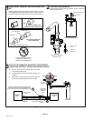
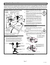
ROUTE HIGH VOLTAGE AND GROUND WIRES
CONTROL BOX
PIPING PANEL
HIGH VOLTAGE
CONDUIT HOLE
GROUND LUG
CONTACTOR
WATERTIGHT
CONDUIT
FITTING
WATERTIGHT
FLEXIBLE
CONDUIT
TO SERVICE
DISCONNECT BOX
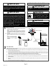
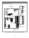
ACCESS VIEW
ELECTRICAL INLET
(HIGH VOLTAGE)
WIRING ENTRY POINTS
ELECTRICAL INLET (CONTROL WIRING Ċ LOW VOLTAGE).
USE BUSHING PROVIDED IN BAG ASSEMBLY HERE.
4