


Page 50
506586−01 10/10
HEAT PUMP CONTROL (A175) UNIT NOMINAL
CAPACITY CODE CONFIGURATION
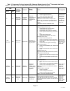
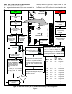
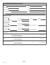
In a communicating system, if the room thermostat is
indicating either a error code 313, indoor and outdoor unit
capacity mismatch error code, or error code 34, must
program unit capacity for outdoor unit. Use the procedure
provided in figure 36 to set the unit nominal capacity code.
When the required Unit Capacity Code
is displaying on the LEDs, remove
FIELD TEST jumper from pins (E33).
LEDs will continue to display the
selected unit capacity code for two (2) minutes
before defaulting back to the idle mode
{simultaneous slow flash}, or until the 24 volt
power is cycled to the air conditioner control.
START
Set room thermostat
to OFF
Go to control terminal
strip
Remove R wire
from control (24 volt
AC power)
icomfort
®
enabled Ċ
Remove control
wires from i+ and
i− terminals
Non − icomfort
®
enabled Ċ
Remove control
wire from Y1
terminal
Place jumper on
FIELD TEST
(E33 pins)
Connect R wire to control
(24 volt AC power)
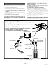
DS14 (Red)
DS11 (Green)
TERMINAL STRIP
Status LED lights DS11
and DS14 will blink and
then on continuously.
Once both LEDs are on
continuously then remove
jumper immediately from
E33.
Place jumper on FIELD
TEST (E33 pins) within 2 to 4
seconds after removal
The control´s DS11 and DS14 LEDs will
start blinking the Unit Nominal Code at
three (3) second intervals starting at 1−ton
through to 6−ton. If a code is not selected,
the control will cycle one more time
through the codes before defaulting back
to the idle mode (simultaneous slow
flash).
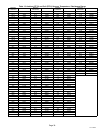
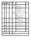
Long blink ON red LED (DS14) to indicate
tonnage and solid ON green LED (DS11)
to indicate ½ tonnage.
Model
DS11
Green
LED
Size
DS14
Red LED
−012
−018
−024
−030
−036
−042
−048
−054
−060
−066
−072
1−ton
1.5−ton
2−ton
2.5−ton
3−ton
3.5−ton
4−ton
4.5−ton
5−ton
5.5−ton
6.0−ton
OFF
ON
OFF
ON
OFF
ON
OFF
ON
OFF
ON
OFF
1 long flash
1 long flash
2 long flashes
2 long flashes
3 long flashes
3 long flashes
4 long flashes
4 long flashes
5 long flashes
5 long flashes
6 long flashes
FINISH
Field Test
(E33)
DS12
Communicating
Status Indicator
Sensor harness
must be attached
to air conditioner
control.
Remove R wire from
air conditioner control
(24 volt AC power)
Connect R wire to
control (24 volt AC
power)
Reconnect any control
wiring previously
removed.
If jumper is not removed
immediately from E33, then DS11
and DS14 LEDs will resume
blinking again.
Remove R wire
from control (24 volt
AC power)
Jumper
removed
successfully
YES
NO
Figure 36. Heat Pump Control (A175) Unit Nominal Capacity Code Configuration