


Page 45
XP17 SERIES
Field Configuration and Testing
This section provides procedures for configuring,
adjusting and testing various components of this unit.
S Fan Motor (B4) Testi Procedure
S Fan Motor Control (A177) Configuration and Testing
S Top Grille and Fan Motor Mounting Adjustment (Fan
Clearance)
S Heat Pump Control (A175) Unit Nominal Capacity
Code configuration
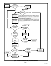
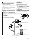
FAN MOTOR (B4) TEST PROCEDURE
The following procedure can be used to test the fan
motor operation. A fully charged 9V battery will be
required for this procedure. See figure 31 for complete
test procedure.
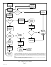
FAN MOTOR CONTROL (A177) OPERATION, AND
TROUBLESHOOTING
This section provides information concerning operation
and testing of the fan control.
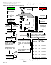
Fan Motor Control Sequence of Operation
During start up, the following sequence is followed:
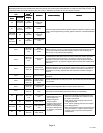
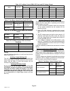
1. Display error conditions (see table 17), if present.
2. If no errors are detected, the LED code indicating
stage operation (see table 18) will display the
applicable code and then a long pause.
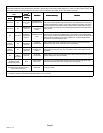
3. The fan motor speed / RPM (revolutions per minute)
indicator is displayed next (see table 16).
4. There is a short pause.
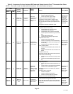
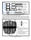
The above sequence will continue to repeat if a thermostat
demand is present. See figure 32 for LED sequence and
table 18 for description of flash and pause durations.
J2
FAN PWM OUT
PARK
COM
BLACK LEAD
BROWN LEAD
BROWN LEAD
BLACK LEAD
REMOVE BOTH LEADS
FROM J2 TERMINALS
CONNECT B4 FAN
MOTOR BLACK COMMON
WIRE TO 9V BATTERY
NEGATIVE TERMINAL
FAN MOTOR CONTROL
BLACK LEAD
BROWN LEAD
FULLY CHARGED
9V BATTERY
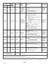
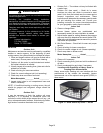
This is a test that will verify that the motor does operate.
1. Verify main (240 volt) power if OFF to unit.
2. Remove both wires (brown and black) from the J2 terminal on the fan motor
control (A177).
3. Room thermostat should be in OFF position (unit in idle mode − no heating or
cooling demands)
4. Turn main power (240 volt) ON to unit.
5. Connect 9 Volt battery to fan motor plugs as noted in picture below.
6. Fan motor should run at a reduced fan speed.
7. If fan motor does not run, then replace fan motor assembly.
NEGATIVE TERMINAL
POSITIVE TERMINAL
CONNECT B4 FAN MOTOR
WIRE TO 9V BATTERY
POSITIVE TERMINAL
V
Figure 31. Fan Motor (B4) Test