


Page 40
506586−01 10/10
System Status, Fault and Lockout LED
Codes
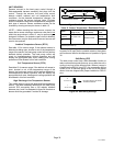
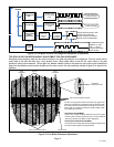
LED codes are displayed using various LEDs located on
the heat pump control (A175). See figure 16 for locations of
heat pump control LEDs.
DS11 AND DS14 Ċ SYSTEM STATUS, FAULT AND
LOCKOUT LED CODES
DS11 (Green) and DS14 (Red) LEDs indicate
non−communicating mode diagnostics conditions that are
listed in table 14.
These LEDs display the most common fault conditions in
the system. When an abnormal condition is detected, this
function communicates the specific condition through
system LED alert codes The function is capable of
detecting both mechanical and electrical system
problems.
DS15 AND DS13 Ċ COMPRESSOR FAULT AND
LOCKOUT LED CODES
DS15 (Yellow) and DS13 (Red) LEDs indicate
non−communicating mode diagnostics conditions that are
listed in table 15.
These LEDs display the most common fault conditions in
the system. When an abnormal condition is detected, this
function communicates the specific condition through
system LED alert codes The function is capable of
detecting both mechanical and electrical system
problems.
IMPORTANT
DS15 and DS13 compressor LED fault and lockout
codes do not provide safety protection. The is a
monitoring function only and cannot control or shut down
other devices.
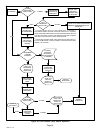
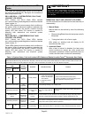
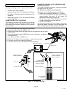
RESETTING FAULT AND LOCKOUT LED CODES
All LED fault and lockout codes can be reset manually or
automatically:
1. Manual Reset
Manual reset can be achieve by one of the following
methods:
S Disconnecting R wire from the heat pump control’s
R terminal.
S Turning the indoor unit off an on again
After power up, existing code will display for 60
seconds and then clear.
2. Automatic Reset
After a fault or lockout is detected, the heat pump
control continues to monitor the unit’s system and
compressor operations. When/if conditions return to
normal, the alert code is turned off automatically.
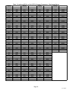
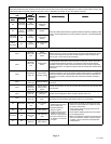
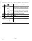
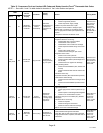
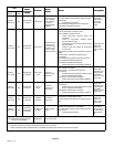
Table 14. System Status, Fault and Lockout LED Codes and Related icomfort Touch
®
Thermostat Alert Codes
System fault and lockout LED (DS11 / DS14) alarm codes takes precedence over system status LED codes (cooling, heating stages or
defrost/dehumidification). Only the latest active LED fault or lockout alarm code if present will be displayed. If no fault or lockout codes are active, then
system status LEDs are routinely displayed. See notes 1 and 2 in table below for duration of fast / slow flashes and pause.
Heat Pump Control
LEDs
icomfort
Touch
®
Thermostat
Display
Condition Possible Cause(s) Solution
DS11
Green
DS14 Red
SYSTEM STATUS
Off Off
Not
applicable
Power problem
1. No power (24V) to heat
pump control terminal’s
R and C or heat pump
control failure.
2. Heat pump control
failure.
1
Check control transformer power (24V).
2
If power is available to control and LED(s) do not
light, replace the heat pump control.
Simultaneous slow flash
Not
applicable
Normal operation Unit operating normally or in standby mode.
Alternating slow flash
Not
applicable
5−minute
anti−short cycle
delay
Initial power up, safety trip,
end of room thermostat de-
mand.
None required (Jumper FIELD TEST (E33) pins to
override)
Simultaneous fast
flashes
Moderate /
Critical Alert
Code 180
Ambient sensor
problem
If sensor detects an open, shorted or out−of−temperature range. heat pump control
will revert to time/temperature defrost operation. System will still heat or cool.
Alternating fast flash
Moderate /
Critical Alert
Code 417
Coil sensor
problem
If the outdoor coil temperature sensor is detected as being open or shorted, the heat
pump control will not perform defrost operations.
On On
Not
applicable
Heat pump
control failure
Indicates that heat pump control has an internal component failure. Cycle 24 volt
power to heat pump control. If code does not clear, replace the heat pump control.