


Page 28
506586−01 10/10
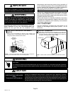
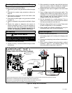
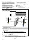
ADDING OR REMOVING REFRIGERANT
This system uses HFC−410A refrigerant which operates at
much higher pressures than HCFC−22. The pre−installed
liquid line filter drier is approved for use with HFC−410A
only. Do not replace it with components designed for use
with HCFC−22.
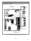
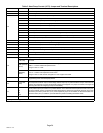
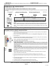
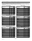
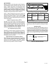
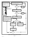
COOLING MODE INDOOR AIRFLOW CHECK
Check airflow using the Delta−T (
DT) process using the
illustration in figure 20.
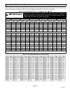
HEATING MODE INDOOR AIRFLOW CHECK
Blower airflow (CFM) may be calculated by energizing
electric heat and measuring:
S Temperature rise between the return air and supply air
temperatures at the indoor coil blower unit,
S Measuring voltage supplied to the unit,
S Measuring amperage being drawn by the heat unit(s).
Then, apply the measurements taken in following formula
to determine CFM:
CFM =
Amps x Volts x 3.41
1.08 x Temperature rise (F)
Cº T
DROP
– DT = ºF ACTION
53º 19 – 15 = 4 INCREASE THE AIRFLOW
58º 14 – 15 = −1 (WITHIN +3º RANGE) NO CHANGE
62º 10 – 15 = −5 DECREASE THE AIRFLOW
DT
80 24 24 24 23 23 22 22 22 20 19 18 17 16 15
78 23 23 23 22 22 21 21 20 19 18 17 16 15 14
76 22 22 22 21 21 20 19 19 18 17 16 15 14 13
74 21 21 21 20 19 19 18 17 16 16 15 14 13 12
72 20 20 19 18 17 17 16 15 15 14 13 12 11 10
70 19 19 18 18 17 17 16 15 15 14 13 12 11 10
57 58 59 60 61 62 63 64 65 66 67 68 69 70
TEMPERATURE OF AIR
ENTERING INDOOR COIL ºF
INDOOR COIL
DRY BULB
DRY
BULB
WET BULB
B
T
DROP
19º
A
DRY−BULB
WET−BULB ºF
A
72º
B
64º
C
53º
AIR FLOWAIR FLOW
All temperatures are expressed in ºF
1. DETERMINE THE DESIRED DT Ċ MEASURE ENTERING AIR TEMPERATURE USING DRY BULB (A) AND WET BULB (B). DT IS THE INTERSECTING VALUE
OF A AND B IN THE TABLE (SEE TRIANGLE).
2. Find temperature drop across coil Ċ Measure the coil’s dry bulb entering and leaving air temperatures (A and C). Temperature Drop Formula:
(T
Drop
) = A minus C.
3. Determine if fan needs adjustment Ċ If the difference between the measured T
Drop
and the desired DT (T
Drop
–DT) is within +3º, no adjustment
is needed. See example below:
4. ADJUST THE FAN SPEED Ċ See indoor unit instructions to increase/decrease fan speed.
ASSUME DT = 15 AND A TEMP. = 72º, THESE C TEMPERATURES WOULD NECESSITATE STATED ACTIONS:
AIRFLOW
Use the following procedure to adjust for optimal air flow across the indoor coil:
INDOOR COIL
Changing air flow affects all temperatures; recheck temperatures to
confirm that the temperature drop and DT are within +3º.
Figure 20. Checking Indoor Airflow over Evaporator Coil using Delta−T Chart Formula