


Page 29
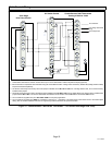
XP17 SERIES
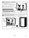
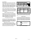
Use WEIGH IN method for adding initial refrigerant charge, and then use SUBCOOLING method for for verifying
refrigerant charge.
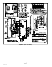
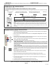
WEIGH IN
LIQUID LINE SET DIAMETER
OUNCES PER 5 FEET (G PER 1.5 M) ADJUST FROM 15 FEET (4.6 M)
LINE SET*
3/8" (9.5 MM)
3 OUNCE PER 5’ (85 G PER 1.5 M)
*If line length is greater than 15 ft. (4.6 m), add this amount. If line length is less than 15 ft. (4.6 m), subtract this
amount.
Refrigerant Charge per Line Set Length
NOTE Ċ The above nameplate is for illustration purposes only. Go to actual nameplate on outdoor unit for charge
information.
CHARGING METHOD
NOTE Ċ Insulate liquid line when it is routed through areas where the surrounding ambient temperature could
become higher than the temperature of the liquid line or when pressure drop is equal to or greater than 20 psig.
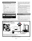
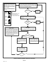
CALCULATING SYSTEM CHARGE FOR OUTDOOR UNIT VOID OF CHARGE
If the system is void of refrigerant, first, locate and repair any leaks and then weigh in the refrigerant charge into the unit. To calculate the total refriger-
ant charge:
Amount specified on
nameplate
Adjust amount. for variation in line set
length listed on line set length table below.
Additional charge specified per indoor
unit match−ups starting on page 30.
Total Charge
+
+
=
Figure 21. Using HFC−410A Weigh In Method
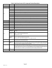
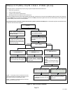
1. Check the airflow as illustrated in figure 20 to be sure the indoor airflow is as required. (Make any air flow adjustments
before continuing with the following procedure.)
2. Measure outdoor ambient temperature; determine whether to use cooling mode or heating mode to check charge.
3. Connect gauge set.
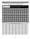
4. Check liquid and vapor line pressures. Compare pressures with either heat or cooling mode normal operating
pressures in table 10, Normal Operating Pressures, High Stage.
NOTE Ċ The reference table is a general guide. Expect minor pressure variations. Significant differences may
mean improper charge or other system problem.
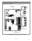
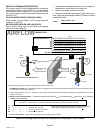
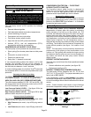
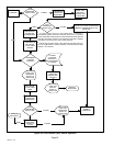
5. Set thermostat for heat/cool demand, depending on mode being used:
USE
COOLING
MODE
USE
HEATING
MODE
60ºF
(15ºC)
SATº
LIQº –
SCº =
SUBCOOLING
6. Read the liquid line temperature; record in the LIQº space.
7. Read the liquid line pressure; then find its corresponding temperature in the temperature/ pressure chart listed
in table 11 and record it in the SATº space.
8. Subtract LIQº temperature from SATº temperature to determine subcooling; record it in SCº space.
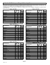
9. Compare SCº results with tables 4 through 9, being sure to note any additional charge for line set and/or match−
up.
10. If subcooling value is greater than shown in tables 4 through 9 for the applicable unit, remove refrigerant; if less
than shown, add refrigerant.
11. If refrigerant is added or removed, repeat steps 5 through 6 to verify charge.
12. Disconnect gauge set and re−install both the liquid and suction service valve caps.
USING COOLING MODE Ċ When the outdoor ambient temperature is 60°F (15°C) and above. Target
subcooling values (second stage − high capacity) in table 10 are based on 70 to 80°F (21−27°C) indoor return air
temperature; if necessary, operate heating to reach that temperature range; then set thermostat to cooling mode
setpoint to 68ºF (20ºC) which should call for second−stage (high stage) cooling. When pressures have stabilized,
continue with Step 6.
USING HEATING MODE Ċ When the outdoor ambient temperature is below 60°F (15°C). Target subcooling
values (second−stage − high capacity) in table 10 are based on 65−75°F (18−24°C) indoor return air temperature;
if necessary, operate cooling to reach that temperature range; then set thermostat to heating mode setpoint to
77ºF (25ºC) which should call for second−stage (high stage) heating. When pressures have stabilized, continue
with Step 6.
CHARGING METHOD
Figure 22. Using HFC−410A Subcooling Method Ċ High Stage (High Capacity)