


Page 32
506586−01 10/10
System Operations
IMPORTANT
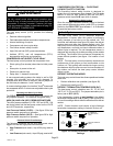
Some scroll compressor have internal vacuum protector
that will unload scrolls when suction pressure goes
below 20 psig. A hissing sound will be heard when the
compressor is running unloaded. Protector will reset
when low pressure in system is raised above 40 psig. DO
NOT REPLACE COMPRESSOR.
The heat pump control (A175) provides the following
functions:
S Demand defrost algorithm
S Field−selectable defrost termination temperatures
S Internal switching of outputs
S Compressor anti−short−cycle delay.
S Five strikes lockout safety function
S High (S4) and low (S87) pressure switches
S Ambient (RT13), and coil temperatures (RT21)
temperature monitoring and protection.
COMPRESSOR ANTI−SHORT CYCLE DELAY
The heat pump control protects the compressor from:
S Short cycling (five minutes) when there is initial power
up
S Interruption in power to the unit
S Pressure or sensor trips
S Delay after Y1 demand is removed.
In non−communicating systems the delay is set for 300
seconds (five minutes) and can not be changed. To
override timer when active or inactive, place a jumper on
the field test pins between 1 and 2 seconds.
In communicating system, the icomfort Touch
®
thermostat
has a separate built−in 5−minute non−adjustable short cycle
protection.
Resetting Anti−Short Cycle Delay
The FIELD TEST pins (E33) on the heat pump control can
be jumpered between 1 to 2 seconds to bypass delay.
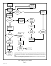
HIGH (S4) AND LOW (S87) PRESSURE SWITCHES
The unit’s pressure switches (LO PS − S87 and HI PS − S4)
are factory−wired into the heat pump control on the LO−PS
and HI−PS terminals, respectively.
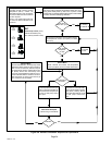
Low Pressure Switch (LO−PS) Ċ See figure 28 for low
pressure switch sequence of operation.
High Pressure Switch (HI−PS) Ċ See figure 29 for high
pressure switch sequence of operation.
Pressure Switch Event Settings
The following pressures are the auto reset event value
triggers for low and high pressure thresholds:
S High Pressure (auto reset) − trip at 590 psig; reset at
418.
S Low Pressure (auto reset) − trip at 25 psig; reset at 40.
COMPRESSOR PROTECTION Ċ FIVE−STRIKE
LOCKOUT SAFETY FUNCTION
The five−strike lockout safety function is designed to
protect the unit’s compressor from damage. The five−strike
feature is used for high pressure (S4) and low (S87)
pressure switch trips and W input fault or miswire.
Resetting Five−Strike Lockout
Once the condition has been rectified, power to the heat
pump control’s R terminal must be cycled OFF, or a jumper
placed on the FIELD TEST pins between 1− to 2−seconds
to reset the heat pump control.
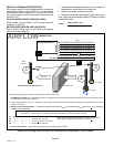
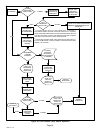
Defrost System
The heat pump control (A175) measures differential
temperatures to detect when the system is performing
poorly because of ice build−up on the outdoor coil. The
controller self−calibrates (see figure 26) when the defrost
system starts and after each system defrost cycle. The
heat pump control monitors ambient temperature, outdoor
coil temperature, and total run−time to determine when a
defrost cycle is required. The coil temperature sensor is
designed with a spring clip to allow mounting to the outside
coil tubing. The location of the coil sensor is important for
proper defrost operation (see figure 1 for location of coil
sensor).
NOTE − The heat pump control accurately measures the
performance of the system as frost accumulates on the
outdoor coil. This typically will translate into longer running
time between defrost cycles as more frost accumulates on
the outdoor coil before the heat pump control initiates
defrost cycles.
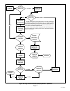
DEFROST OPERATING MODES
The heat pump control board has three operational modes
which are:
S Defrost calibration and operation (see figure 26)
S Defrost test (see figure 27)
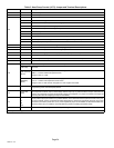
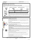
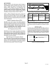
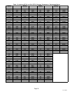
DEFROST TERMINATION TEMPERATURES (E47)
The heat pump control selections are: 50, 70, 90, and
100°F (10, 21, 32 and 38°C). The jumper termination pin is
factory set at 50°F (10°C).
If the temperature jumper is not installed, the default
termination temperature is 90°F (32°C). See figure 26 for
on how this settings affects defrost calibration and defrost
modes.
NOTE − Colder climates could require a high discharge
termination temperature setting to maintain a clear coil.
100
90
DEGREE
TARGET
70
DEGREE
TARGET
50
DEGREE
TARGET
100
90
70
50
DEGREE
TARGET
100
90
70
50
100
90
70
50
100
90
70
50
FACTORY DEFAULT
(50ºF)
IF JUMPER IS
NOT INSTALLED
(90ºF)
Figure 23. Defrost Termination Temperature
Settings