


Page 46
506586−01 10/10
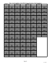
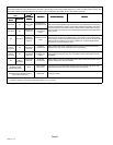
Table 16. Fan Motor Control RPM, LED Code and DC Voltage Output
Model LED Code*
CFM Profile Pin Select ECM1/Y1
4 3 2 1 RPM (J2) DC Volt
XP17−024 5 OFF ON ON ON 400 12.7
XP17−030 6 OFF ON ON OFF 450 14.3
XP17−036, −042 8 OFF OFF ON ON 600 19.2
XP17−048, −060 9 OFF OFF OFF ON 675 21.6
* LED Code indicates fan motor control LED flash sequence. For example, LED Code 9 indicates 9 slow flashes and pause.
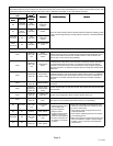
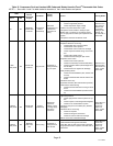
Table 17. Fan Motor Control Error/Fault LED Codes
Unit Status Motor Control LED Possible Cause
Mismatched RPM
Fast flash with no
pause
Internal feedback,
PWM does not
match target
CRC Failure Constant ON.
Microcontroller CRC
failure
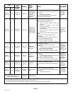
Table 18. 19. Fan Motor Control Stage LED Indicator
Codes
Unit Status Unit Status
Fan Motor Control
LED
One Stage
Operation
Low Stage Ċ
ECM1/Y1 ONLY
One slow flash, then
short pause.
Table 20. Fan Motor Control Flash and Pause
Durations
Flash or Pause State Duration
Flash Flash Three flashes per second
Slow Flash One flash per second
Short Pause Two seconds of OFF time
Long Pause Five seconds of OFF time
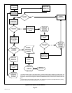
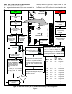
Testing
Use the following subsections to verify and test the fan
motor control (A177).
Verifying Jumper Settings (J2)
The unit is shipped from the factory with the default fan
motor speed setting (in RPMs) required for each specific
model. Use the table 16 verify that jumpers are set
correctly for the specific unit.
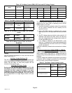
Verifying LED Status Codes
During start up, the fan motor control (A177) LED
will display any error conditions. If error conditions
exist then no other codes will display. If no error
conditions are present, then the stage status and
and RPM indicator are displayed. Fan motor speeds
are not adjustable for a single stage outdoor unit (see
table 16).
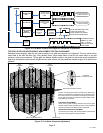
Verifying Correct DC Output Voltage (J2)
The following three methods can be used to determine
whether the fan motor (B4) is operating at the correct
RPMs based on unit size.
1. Use the information provided in table 16 to verify that
all four jumper terminals are set correctly for the
specific size unit.
2. Verify LED RPM indicator is displaying the correct
flash sequence for the applicable size unit (see table
18).
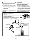
3. Test DC voltage output on the fan motor control’s J2
terminals (see figure 34) while under full load and
verify the voltage read to the voltage listed in table 16
for the applicable size unit.
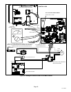
4. If no voltage is detected at the J2 terminals, verify
there is a Y1 demand at the thermostat and applicable
voltages detected all fan motor control (A177) voltage
inputs, see table 21.
If there is a demand, proceed to the next section for further
testing.
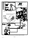
Verifying Correct Input Voltage (ECM/Y1, ECM/Y2,
ECM C and EXT ECM/R)
Using a voltmeter, check voltages on the following fan
motor control inputs using table 21. Voltage will only be
present during a thermostat demand. See figure 35 for test
example.
If correct voltages are detected at applicable inputs during
a demand, and no voltage is present at the J2 terminals,
then fan motor control should be replaced.
Table 21. Fan Motor Control Voltage Inputs
Input
Call for
Cooling
Voltage
Present
ECM/Y1 and ECM C
YES
Between 24VDC
and 32 VDC
NO NONE
EXT ECM/R and ECM C
YES 24VAC
NO NONE