


Page 27
XP17 SERIES
Servicing Units Delivered Void of Charge
If the outdoor unit is void of refrigerant, clean the system
using the procedure described below.
1. Leak check system using procedure outlined on page
18.
2. Evacuate the system using procedure outlined on
page 19.
3. Use nitrogen to break the vacuum and install a new
filter drier in the system.
4. Evacuate the system again using procedure outlined
on page 19.
5. Weigh in refrigerant using procedure outlined in figure
21.
6. Monitor the system to determine the amount of
moisture remaining in the oil. It may be necessary to
replace the filter drier several times to achieve the
required dryness level. If system dryness is not
verified, the compressor will fail in the future.
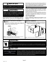
Unit Start−Up
IMPORTANT
If unit is equipped with a crankcase heater, it should be
energized 24 hours before unit start−up to prevent
compressor damage as a result of slugging.
1. Rotate fan to check for binding.
2. Inspect all factory− and field−installed wiring for loose
connections.
3. After evacuation is complete, open both the liquid and
vapor line service valves to release the refrigerant
charge contained in outdoor unit into the system.
4. Replace the stem caps and tighten to the value listed
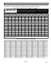
in table 1.
5. Check voltage supply at the disconnect switch. The
voltage must be within the range listed on the unit’s
nameplate. If not, do not start the equipment until you
have consulted with the power company and the
voltage condition has been corrected.
6. Set the thermostat for a cooling demand. Turn on
power to the indoor indoor unit and close the outdoor
unit disconnect switch to start the unit.
7. Recheck voltage while the unit is running. Power must
be within range shown on the nameplate.
8. Check system for sufficient refrigerant by using the
procedures listed under System Refrigerant.
System Refrigerant
This section outlines procedures for:
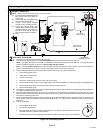
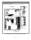
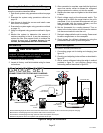
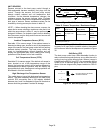
1. Connecting gauge set for testing and charging (see
figure 19.
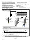
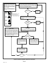
2. Checking and adjusting indoor airflow as described in
figure 20.
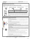
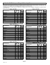
3. Add or remove refrigerant using the weigh in method
provided in figure 21, and verifying charge using
subcooling method described in figure 22.
TO LIQUID
LINE SERVICE
VALVE
TEMPERATURE
SENSOR
DIGITAL SCALE
REFRIGERANT TANK
TEMPERATURE SENSOR
(LIQUID LINE)
MANIFOLD GAUGE SET
AClose manifold gauge set valves and connect the center hose to a cylinder of HFC−410A. Set for liquid phase charging.
BConnect the manifold gauge set’s low pressure side to the true suction port.
CConnect the manifold gauge set’s high pressure side to the liquid line service port.
DPosition temperature sensor on liquid line near liquid line service port.
OUTDOOR UNIT
CHARGE IN
LIQUID PHASE
CONNECTIONS FOR TESTING AND CHARGING
GAUGE SET
A
C
D
LOW
HIGH
B
INSIDE OUTDOOR UNIT
TRUE SUCTION PORT
CONNECTION
Figure 19. Gauge Set Connections