


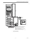

7800 SERIES EC7895A, RM7895A RELAY MODULE
65-0205
8
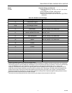
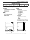
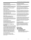
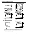
Fig. 4. Ultraviolet detectorsin in. (mm)
(Continued).
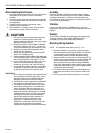
15/16 [24] DIA.
2 (51)
1 (25)
1 INCH NPT
15/16–18 UNC
(2 EACH)
M5084A
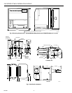
2-1/2
(64)
6-7/32
(158)
6-19/32
(168)
2-5/32
(55)
11-13/16 (300)
7-13/16 (198)
1-27/32
(47)
5-13/16 (147)
5-13/16
(147)
C7076D
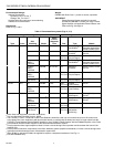
Fig. 5. Infrared detector in in. (mm).
PRINCIPAL TECHNICAL FEATURES
The EC7895 or RM7895 provides all customary flame
safeguard functions while providing significant advancements
in the areas of safety, annunciation and system diagnostics.
Safety Shutdown (Lockout) Occurs If:
1. Initiate Period
a. Purge card is not installed or removed.
b. Purge card is bad.
c. Configuration jumpers have been changed (after
200 hours).
d. AC line power errors occurred, see Operation.
e. Four minute INITIATE period was exceeded.
2. Standby Period
a. Flame signal is present after 40 seconds.
b. Ignition/pilot valve/intermittent pilot valve terminal
is energized.
c. Main valve terminal is energized.
d. Internal system fault occurred.
e. Purge card is not installed or removed.
f. Purge card is bad.
3. Prepurge Period
a. Airflow lockout feature is enabled and the airflow
switch does not close after ten seconds or within
the specified purge card timing.
b. Flame signal is detected after 30 seconds.
c. Ignition/pilot valve/intermittent pilot valve terminal
is energized.
d. Main valve terminal is energized.
e. Internal system fault occurred.
f. Purge card is removed.
g. Purge card is bad.
4. Pilot Flame Establishing Period (PFEP)
a. Airflow lockout feature is enabled and the airflow
switch opens.
b. Ignition/pilot valve terminal is not energized.
c. No flame present at end of PFEP.
d. Main valve terminal is energized.
e. Internal system fault occurred.
f. Purge card is removed.
g. Purge card is bad.
5. Run Period
a. No flame present.
b. Airflow lockout feature is enabled and the airflow
switch opens.
c. Main valve terminal is not energized.
d. Internal system fault occurred.
e. Purge card is removed.
f. Purge card is bad.
SAFETY PROVISIONS
Internal Hardware Status Monitoring
The EC7895 or RM7895 checks the purge card for correct
parity to prevent purge timing shifts and circuitry failures. It
also analyzes the integrity of the configuration jumpers and
internal hardware. The POWER LED blinks every four
seconds, signifying an internal hardware check.
Closed Loop Logic Test
The test verifies the integrity of all safety critical loads,
terminals 8, 9, 10 and 21. If the loads are not energized
properly; i.e., the main valve terminal is powered during
PREPURGE, the EC7895 or RM7895 locks out on safety
shutdown. The EC7895 or RM7895 must react to input
changes but avoid the occurrence of
nuisance
shutdown
events. Signal conditioning is applied to line voltage inputs to
verify proper operation in the presence of
normal
electrical
line noise such as transient high voltage spikes or short
periods of line dropout. Signal conditioning is tolerant of
synchronous noise (line noise events that occur at the same
time during each line cycle).
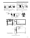
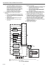
APERTURE
BUSHING WITH
MAGNIFYING LENS
COLLAR, 3/4-14 NPSM
INTERNAL THREADS
3/4-14
NPSM
3/4-14 NPSM
INTERNAL
THREADS
HEAT BLOCKCELL MOUNT
M1982A
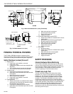
2 LEADS IN A
48 INCH (1.2 METER)
FLEXIBLE CONDUIT
2-3/4
(70)
1-1/4
(32)
1-5/8 (41)
1-1/16 (27)
1-1/4
(32)
C7015