


7800 SERIES EC7895A, RM7895A RELAY MODULE
65-0205
22
NOTE: Low fuel pressure limits, if used, could be open. If
so, bypass them with jumpers during this check.
1. Open the master switch.
2. Make sure that the manual main fuel shutoff valve(s) is
closed. Open the manual pilot shutoff valve. If the pilot
takeoff is downstream from the manual main fuel
shutoff valve(s), very slightly open the manual main
valve to supply pilot gas flow. Make sure the main fuel
is shutoff just upstream from the burner inlet, or
disconnect power from the automatic main fuel
valve(s).
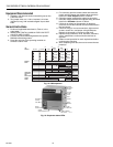
3. Close the master switch and start the system with a
call
for heat
by raising the set point of the operating
controller, see Fig. 15. The primary sequence should
start the ten-second INITIATE sequence.
4. Let the sequence advance through PREPURGE.
Ignition spark should occur and the pilot should light. If
the pilot ignites, the FLAME LED is energized. Proceed
to step 7.
5. If the pilot flame is not established in four or ten
seconds, safety shutdown occurs. Let the sequence
complete its cycle. Consult the equipment operating
manual for further information.
6. Push the reset pushbutton, and let the system recycle
once. If the pilot still does not ignite, make the following
ignition/pilot adjustments:
a. Open the master switch and remove the EC7895
or RM7895 from the subbase.
b. On the subbase, jumper terminal 5 to ignition
terminals 8 or 10; refer to the appropriate wiring
diagram to determine the proper terminal.
Disconnect the leadwire to the pilot valve if it is
connected to the same terminal.
c. Close the master switch to energize only the
ignition transformer.
d. If the ignition spark is not strong and continuous,
open the master switch and adjust the ignition
electrode spark gap setting to the manufacturer
recommendations.
e. Make sure the ignition electrodes are clean.
f. Close the master switch and observe the spark.
g. After a continuous spark is obtained, open the
master switch and add a jumper on the subbase
from terminal 5 (L1) to the pilot terminal 8.
Reconnect the leadwire from the pilot valve if it
was disconnected in step b.
h. Close the master switch to energize both the
ignition transformer and the pilot valve.
i. If the pilot does not ignite and if the ignition spark
is still continuous, adjust the pressure regulator
until a pilot is established.
j. When the pilot ignites properly and stays ignited,
open the master switch and remove the jumper(s)
from terminals 5 through 8 or 5 through 10 of the
subbase.
k. Check for adequate bleeding of the fuel line.
l. Reinstall the EC7895 or RM7895 on the subbase
and close the master switch, then return to step 4.
7. When pilot ignites, measure the flame signal. If the pilot
flame signal is unsteady or approaching the 1.25 Vdc
minimum value, adjust the pilot flame size or detector
sighting to provide a maximum and steady flame signal.
8. Recycle the system to recheck lightoff and pilot flame
signal.
9. When the MAIN IGN period is displayed by the MAIN
LED, make sure the automatic main fuel valve is open;
then smoothly open the manual main fuel shutoff
valve(s) and watch for main burner flame ignition.
When the main burner flame is established, proceed to
step 16.
10. If the main burner flame is not established within five
seconds or the normal lightoff time specified by the
equipment manufacturer, close the manual main fuel
shut-off valve(s).
11. Recycle the system to recheck the lightoff and pilot
flame signal.
12. Smoothly open the manual fuel shutoff valve(s) and try
lightoff again. (The first reattempt may have been
required to purge the lines and bring sufficient fuel to
the burner.)
13. If the main burner flame is not established within five
seconds or the normal lightoff time specified by the
equipment manufacturer, close the manual main fuel
shut-off valves(s). Check all burner adjustments.
14. If the main burner flame is not established after two
attempts:
a. Check for improper pilot size.
b. Check for excess combustion air.
c. Check for adequate fuel flow.
d. Check for proper gas supply pressure.
e. Check for proper valve operation.
f. Check for proper pilot flame positioning.
15. Repeat steps 8 through 14 to establish the main burner
flame; then proceed to step 16.
16. With the sequence in RUN, make burner adjustments
for flame stability and BTU input rating.
17. Shut down the system by opening the burner switch or
by lowering the set point of the operating controller.
Make sure the main flame goes out. There may be a
delay due to gas trapped between the valve(s) and the
burner. Make sure all automatic fuel valve(s) close.
18. Restart the system by closing the burner switch and/or
raising the set point of the operating controller. Observe
that the pilot is established during PILOT IGN and the
main burner flame is established during MAIN IGN
within the normal lightoff time.
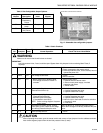
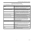
19. Measure the flame signal. Continue to check for the
proper signal, see Table 5, through the RUN period.
20. Run the burner through another sequence, observing
the flame signal for:
a. Pilot flame alone (unless using direct spark
ignition).
b. Pilot and main flame together.
c. Main flame alone (unless monitoring an
intermittent pilot).
Also observe the time it takes to light the main flame. Ignition
of main flame should be smooth.
21. Return the system to normal operation.
22. Make sure all readings are in the required ranges be-
fore proceeding.
NOTE: Upon completing these tests, open the master
switch and remove all test jumpers from the subbase
terminals, limits/controls or switches.