


7800 SERIES EC7895A, RM7895A RELAY MODULE
65-0205
10
When Installing this Product…
1. Read these instructions carefully. Failure to follow them
could damage the product or cause a hazardous
condition.
2. Check the ratings given in the instructions and marked
on the product to make sure the product is suitable for
your application.
3. Installer must be a trained, experienced, flame
safeguard service technician.
4. After installation is complete, check out the product
operation as provided in these instructions.
CAUTION
1. Disconnect the power supply before beginning
installation to prevent electrical shock and
equipment damage. More than one power supply
disconnect may be involved.
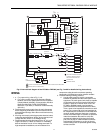
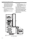
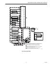
2. Wiring connections for the EC7895 or RM7895
are unique; therefore, refer to Fig. 7 or 8 for the
correct Specifications for proper subbase wiring.
3. Wiring must comply with all applicable codes,
ordinances and regulations.
4. Wiring, where required, must comply with NEC
Class 1 (Line Voltage) wiring.
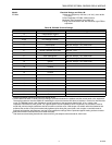
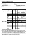
5. Loads connected to the EC7895 or RM7895 must
not exceed those listed on the EC7895 or RM7895
label or the Specifications, see Table 1A or 1B.
6. Limits and interlocks must be rated to carry and
break current simultaneously to the ignition
transformer, pilot valve, and main fuel valve(s).
7. All external timers must be listed or components
recognized by authorities who have jurisdiction
for specific purpose for which they are used.
IMPORTANT
1. For on-off gas-fired systems, some authorities who
have jurisdiction prohibit the wiring of any limit or
operating contacts in series between the flame
safeguard control and the main fuel valve(s).
2. Two Detectors can be connected in parallel with
the exception of Infrared Detectors (C7015).
3. This equipment generates, uses and can radiate
radio frequency energy and, if not installed and
used in accordance with the instructions, may
cause interference to radio communications. It is
designed to meet the requirements for a Class B
computing device of part 15 of FCC rules, which
are designed to provide reasonable protection
against such interference when operated in a
commercial environment. Operation of this
equipment in a residential area may cause
interference; in which case, the user at their own
expense may be required to take whatever
measures are required to correct this interference.
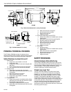
Humidity
Install the EC7895 or RM7895 where the relative humidity
never reaches the saturation point. The EC7895 or RM7895
is designed to operate in a maximum 85% RH continuous,
noncondensing, moisture environment. Condensing moisture
can cause a safety shutdown.
Vibration
Do not install the EC7895 or RM7895 where it could be
subjected to vibration in excess of 0.5G continuous maximum
vibration.
Weather
The EC7895 or RM7895 is not designed to be weather tight.
If installed outdoors, the EC7895 or RM7895 must be
protected by an approved weather-tight enclosure.
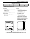
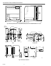
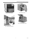
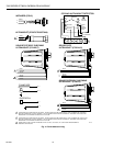
Mounting Wiring Subbase
NOTE: For installation dimensions, see Fig. 1 or 2.
1. Mount the subbase in any position except horizontally
with the bifurcated contacts pointing down. The standard
vertical position is recommended. Any other position
decreases the maximum ambient temperature rating.
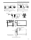
2. Select a location on a wall, burner or electrical panel. The
Q7800 can be mounted directly in the control cabinet. Be
sure to allow adequate clearance for servicing, instal-
lation, access and removal of the EC7895 or RM7895,
Dust Cover, flame amplifier, flame amplifier signal voltage
probes, Run/Test Switch, electrical signal voltage probes
and electrical field connections.
3. For surface mounting, use the back of the subbase as a
template to mark the four screw locations. Drill the pilot
holes.
4. Securely mount the subbase using four no. 6 screws.