


7800 SERIES EC7895A, RM7895A RELAY MODULE
65-0205
20
CHECKOUT
WARNING
Do not allow fuel to accumulate in the combustion
chamber. If fuel is allowed to enter the chamber for
longer than a few seconds without igniting, an
explosive mixture could result. It is recommended that
you limit the trial for pilot to ten seconds, and limit the
attempt to light the main burner two seconds from the
time the fuel has reached the burner nozzle. In any
case, do not exceed the nominal lightoff time specified
by the equipment manufacturer. Close the manual fuel
shutoff valve(s) if the flame is not burning at the end of
the specified time.
CAUTION
1. Use extreme care while testing the system. Line
voltage is present on most terminal connections
when power is on.
2. Open the master switch before removing or
installing the EC7895 or RM7895.
3. Make sure all manual fuel shutoff valve(s) are
closed before starting the initial lightoff check and
the Pilot Turndown tests.
4. Do not put the system in service until you have
satisfactorily completed all applicable tests in this
section and any others required by the equipment
manufacturer.
CAUTION
If an EC7895 or RM7895 is replaced with a lower
or higher functioning 7800 SERIES Relay Module,
the burner will not sequence unless wiring changes
are made.
IMPORTANT
1. If the system fails to perform properly, refer to
7800 SERIES System Annunciation Diagnostics
and Troubleshooting, form 65-0118.
2. Repeat ALL required Checkout tests after all
adjustments are made. ALL tests must be satisfied
with the flame detector(s) in its FINAL position.
Equipment Recommended
Volt-ohmmeter (1M ohm/volt minimum sensitivity):
• 0-300 Vac capability.
• 0-6000 ohm capability.
• 0-10 Vdc capability.
Checkout Summary
• Preliminary inspection—all installations.
• Flame signal measurement—all installations.
• Initial lightoff check for proved pilot—all installations using
a pilot.
• Initial lightoff check for direct spark ignition of oil—all
burners using DSI.
• Pilot turndown test—all installations using a pilot.
• Hot refractory saturation test—all installations using
Infrared (lead sulfide) Flame Detectors.
• Hot refractory hold-in test—all installations.
• Ignition interference test—all installations using flame
rods.
• Ignition spark pickup—all installations using Ultraviolet
Flame Detectors.
• Response to other ultraviolet sources—all installations
using Ultraviolet Flame Detectors.
• Flame signal with hot combustion chamber—all
installations.
• Safety shutdown tests—all installations.
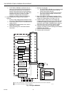
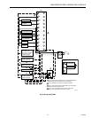
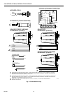
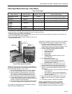
See Fig. 1 and 2 for location of component parts and see Fig.
7 or Q7800 Specifications for terminal locations.
Preliminary Inspection
Perform the following inspections to avoid common problems.
Be sure:
1. Wiring connections are correct and all terminal screws
are tight.
2. Flame detector(s) is clean, installed and positioned
properly. Consult the applicable Instructions.
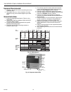
3. Correct combination of amplifier and flame detector is
used (see Table 2).
4. Plug-in amplifier and purge card are securely in place.
5. Burner is completely installed and ready to fire; consult
equipment manufacturer instructions. Fuel lines are
purged of air.
6. Combustion chamber and flues are clear of fuel and
fuel vapor.
7. Power is connected to the system disconnect switch
(master switch).
8. Lockout switch is reset (push in reset pushbutton) only
if the 7895 is powered, see Fig. 1 and 2.
9. System is in the STANDBY condition. POWER LED is
energized.
10. All limits and interlocks are reset.