


7800 SERIES EC7895A, RM7895A RELAY MODULE
65-0205
18
Equipment Recommended
1. Voltmeter (1M ohm/volt minimum sensitivity) set on the
0-300 Vac scale.
2. Two jumper wires; no. 14 wire, insulated, 12 inches
(304.8 mm) long, with insulated alligator clips at both
ends.
General Instructions
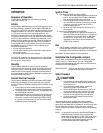
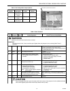
1. Perform all applicable tests listed in, Table 4, in the
order listed.
2.
MAKE SURE THAT ALL MANUAL FUEL SHUT-OFF
VALVE(S) ARE CLOSED.
3. Perform only those tests designated for the specific
RM7895 model being tested.
4. Raise the set point of the operating controller to
simulate a
call for heat.
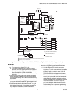
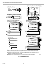
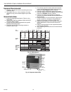
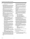
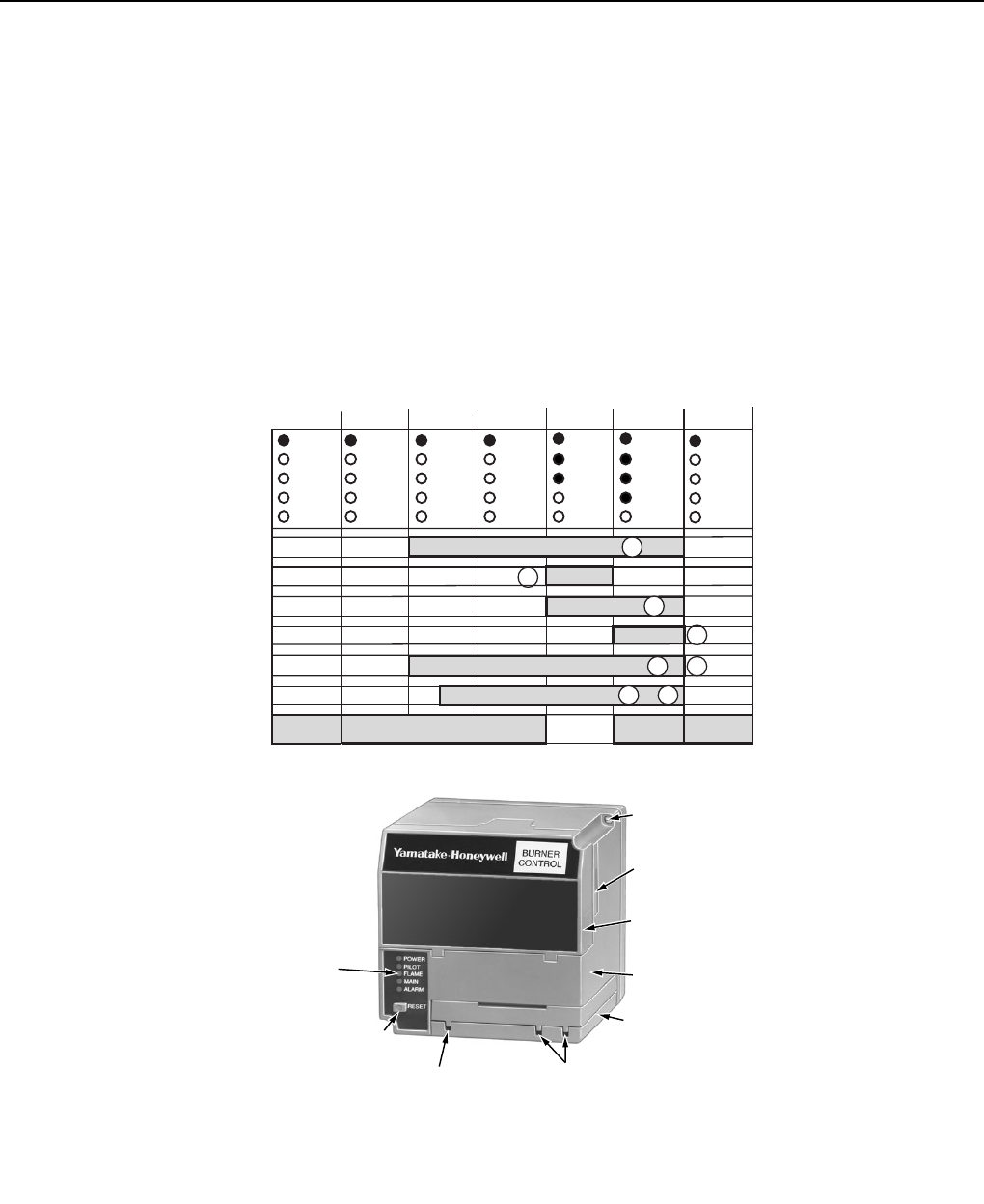
Fig. 15. 7895 sequence.
5. For each test, open the master switch and install the
jumper wire(s) between the subbase wiring terminals
listed in the Test Jumpers column of Table 4.
6. Close the master switch before observing operation.
7. Read the voltage between the subbase wiring terminals
listed in the Voltmeter column of Table 4.
8. If there is no voltage or the operation is abnormal,
check the circuits and external devices as described in
the last column.
9. Check all wiring for correct connections, tight terminal
screws, correct wire, and proper wiring techniques.
Replace all damaged or incorrectly sized wires.
10. Replace faulty controllers, limits, interlocks, actuators,
valves, transformers, motors and other devices as
required.
11. Obtain normal operation for each required test before
continuing the checkout.
12. After completing each test, be sure to remove the test
jumper(s).
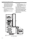
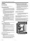
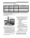
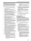
SEQUENCE
STATUS
LEDs
RESET
PUSHBUTTON
FLAME
SIMULATOR INPUT
FLAME CURRENT
TEST JACKS
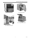
CAPTIVE
MOUNTING
SCREW
PLUG-IN
PURGE
CARD
DUST
COVER
RELAY
MODULE
FLAME
AMPLIFIER
M11127
Fig. 16. Sequence status LEDs.
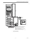
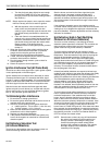
IGN.
OPERATING
CONTROLS
AND
INTERLOCKS
INITIATE
ALARM ALARM
STANDBY
POWER POWER
PILOT
FLAME
MAIN
TIMED
PURGE
ALARM
POWER
PILOT
FLAME
MAIN
RUN
STANDBY
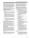
BURNER
START
MAIN VALVE
LIMITS AND BURNER CONTROLLER CLOSED
IGN./ PILOT
SAFE START CHECK
FLAME
PROVING
SSC
LED
DISPLAY
POWER
PILOT
FLAME
MAIN
PFEP
4 OR 10 SEC
POWER
START
POWERPOWER
FLAME
SIGNAL
M11130
00 00 00
10
L1 TO 6
9
8
4
BURNER/BLOWER MOTOR
AIRFLOW INTERLOCK CLOSED
TO 76