


7800 SERIES EC7895A, RM7895A RELAY MODULE
65-0205
14
ASSEMBLY
Mounting RM7895
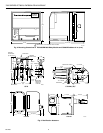
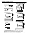
NOTE: For installation dimensions, see Fig. 1 or 2.
Relay Module Mounting
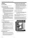
1. Mount the EC7895 or RM7895 vertically, see Fig. 9 or
10, or mount horizontally with the knife blade terminals
pointing downward. When mounted on the Q7800A, the
EC7895 or RM7895 must be in an electrical enclosure,
see Fig. 9.
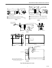
2. Select the location in the electrical enclosure. Be sure
to allow adequate clearance for servicing, installation
and removal of the EC7895 or RM7895, Dust Cover,
flame amplifier, flame amplifier signal voltage probes,
electrical signal voltage probes and electrical
connections.
a. Allow an additional two inches below the EC7895
or RM7895 for the flame amplifier mounting.
b. Allow an optional three-inch minimum to both
sides of the EC7895 or RM7895 for electrical
signal voltage probes.
3. Make sure no subbase wiring is projecting beyond the
terminal blocks. Tuck wiring in against the back of the
subbase so it does not interfere with the knife blade
terminals or bifurcated contacts.
4. Mount the EC7895 or RM7895 by aligning the four L
shaped corner guides and knife blade terminals with
the bifurcated contacts on the wiring subbase and
securley tightening the two screws without deforming
the plastic.
IMPORTANT
Install the EC7895 or RM7895 with a plug-in motion
rather than a hinge action.
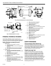
Installing ST7800 Purge Card
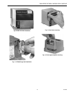
1. Remove the Dust Cover, Keyboard Display Module,
DATA CONTROLBUS MODULE™or Extension Cable
Assembly.
2. Remove the current ST7800 from the EC7895 or
RM7895 by pulling upward on the plastic support cover,
see Fig. 12.
3. Make sure that the ST7800 selected has the desired
timing.
4. Insert the Purge Card into the opening of the RM7895
compartment, see Fig. 11.
5. Reinstall the Dust Cover, Keyboard Display Module,
DATA CONTROLBUS MODULE™ or Extension Cable
Assembly onto the EC7895 or RM7895 and restore
power to the device.
Run the burner system through at least one complete cycle to
verify the system is operating as desired.
Mounting Dust Cover
1. Align the two interlocking ears of the Dust Cover with
the two mating slots on the EC7895 or RM7895, see
Fig. 12.
2. Insert the two interlocking ears into the two mating slots,
and with a hinge action, push on the upper corners of the
Dust Cover to secure it to the EC7895 or RM7895.
3. Be sure the Dust Cover is firmly in place.
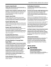
Installing Plug-In Flame Signal Amplifier
1. Disconnect the power supply before beginning
installation to prevent electrical shock and equipment
damage. More than one disconnect may be involved.
2. Align the amplifier circuit board edge connector with the
keyed receptacle on the EC7895 or RM7895. Ensure
the amplifier nameplate faces away from the Relay
Module, see Fig. 13.
3. Push in the amplifier until the circuit board is fully
inserted into the receptacle and then push the amplifier
toward the EC7895 or RM7895 retaining clasp.
4. Verify the amplifier is firmly in place.
5. Perform all required checkout tests.
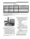
Installing the Flame Detector
NOTE: Table 2 lists the flame detection systems available
for use with the EC7895 or RM7895. Make sure the
correct combination of amplifier and flame
detector(s) is used.
Proper flame detector installation is the basis of a safe and
reliable flame safeguard installation. Refer to the Instructions
packed with the flame detector and the equipment
manufacturer instructions.
Keep the flame signal leadwires as short as possible from the
flame detector to the wiring subbase. Capacitance increases
with leadwire length, reducing the signal strength. The
maximum permissible leadwire length depends on the type of
flame detector, leadwire and conduit. The ultimate limiting factor
in the flame detector leadwire is the flame signal; see Table 5.
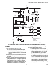
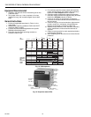
Fig. 9. Electrical panel installation.