


7800 SERIES EC7895A, RM7895A RELAY MODULE
65-0205
25
If the detector is sensing hot refractory, the condition must be
corrected. Add an orifice plate in front of the cell to restrict the
viewing area of the detector. If this does not correct the
problem, resight the detector at a cooler, more distant part of
the combustion chamber. While resighting the detector, be
aware that it must also properly sight the flame. When using
infrared detector, try lengthening the sight pipe or decreasing
the pipe size (diameter). For details, refer to the detector
Instructions and the equipment Operating Manual. Continue
adjustments until hot refractory hold-in is eliminated.
Ultraviolet Sensor, Ignition Spark Response
Test (All Ultraviolet Detectors)
Test to be sure that the ignition spark is not actuating the
FLAME LED:
1. Close the pilot and main burner manual fuel shutoff
valve(s).
2. Start the burner and run through the PILOT IGN period.
Ignition spark should occur, but the flame signal should
not be more than 0.5 Vdc and the FLAME LED should
not turn on.
3. If the flame signal is higher than 0.5 Vdc and the
FLAME LED does come on, consult the equipment
Operating Manual and resight the detector further out
from the spark, or away from possible reflection. It may
be necessary to construct a barrier to block the ignition
spark from the detector view. Continue adjustments
until the flame signal due to ignition spark is less than
0.5 Vdc.
NOTE: The Honeywell Q624A Solid State Spark Generator
prevents detection of ignition spark when properly
applied with the C7027, C7035 or C7044 Minipeeper
Ultraviolet Flame Detectors. The Q624A is only for
use with gas pilots.
Response To Other Ultraviolet Sources
Under certain conditions, an ultraviolet detector responds to
other ultraviolet sources as if it is sensing a flame. These
ultraviolet sources include artificial light, such as
incandescent or fluorescent bulbs, mercury and sodium vapor
lamps or daylight. To check for proper detector operation,
check the Flame Failure Response Time (FFRT) and conduct
Safety Shutdown tests under all operating conditions.
Flame Signal With Hot Combustion Chamber
(All Installations)
After all initial start-up tests and burner adjustments are
completed, operate the burner until the combustion chamber
is at the maximum expected temperature. Observe the
equipment manufacturer warmup instructions. Recycle the
burner under these hot conditions and measure the flame
signal. Check the pilot alone, the main burner flame alone,
and both together (unless monitoring only the pilot flame
when using an intermittent pilot, or only the main burner flame
when using DSI).
Check the FFRT of the Flame Amplifier. Lower the set point of
the operating controller and observe the time it takes for the
burner flame to go out. This should be within .8 or 3 seconds
maximum depending on the amplifier selected.
If the flame signal is too low or unsteady, check the flame
detector temperature. Relocate the detector if the
temperature is too high. If necessary, realign the sighting to
obtain the proper signal and response time. If the response
time is still too slow, replace the Plug-in Flame Signal
Amplifier. If the detector is relocated or resighted, or the
amplifier is replaced, repeat all required Checkout tests.
Safety Shutdown Tests (All Installations)
Perform these tests at the end of Checkout after all other
tests are complete. If used, the external alarm should turn on.
Press the RM7895 reset pushbutton to restart the system.
1. Close the Airflow Interlock during PREPURGE, PILOT
IGN, MAIN IGN or RUN period.
a. Safety shutdown occurs if the Airflow ILK Switch
Failure configuration jumper (JR3) is clipped.
2. Detect flame 40 seconds after entry to STANDBY. Detect
flame 30 seconds during measured PREPURGE time.
a. Simulate a flame to cause the flame signal voltage
level to be at least 1.25 Vdc for 40 seconds after
entry to STANDBY and also simulate a flame
signal for 30 seconds during PREPURGE.
b. Safety shutdown occurs.
3. Failure to ignite pilot.
a. Close the pilot and main fuel manual shutoff
valve(s).
b. Depress the reset push button.
c. Start the system.
d. Automatic pilot valve(s) should be energized but
the pilot cannot ignite.
e. Safety shutdown occurs.
4. Failure to ignite main.
a. Open the manual pilot valve(s); leave the main
fuel manual shutoff valve(s) closed.
b. Depress the reset pushbutton.
c. Start the system.
d. Pilot should ignite and the flame signal should be
at least 1.25 Vdc but the main burner cannot light.
e. Close the manual pilot valve(s).
f. Flame signal should drop below 1.25 Vdc within
.8 or 3 seconds (depending on the FFRT of the
amplifier) after the pilot goes out.
g. Safety shutdown occurs.
5. Loss of flame during RUN.
a. Open the main fuel manual shutoff valve(s). The
manual pilot shutoff valve(s) must also be opened.
b. Depress the reset push button.
c. Start the system. Startup should be normal and
the main burner should light normally.
d. After the sequence is in the normal RUN period
for at least ten seconds with the main burner
firing, close the manual main and pilot fuel shutoff
valve(s) to extinguish the main burner flame.
e. The flame signal should drop below 1.25 Vdc
within .8 or 3 seconds (depending on the FFRT of
the amplifier) after the main flame goes out.
f. Safety shutdown occurs.
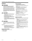
IMPORTANT
1. If the EC7895 or RM7895 fails to shut down on
any of these tests, take corrective action (refer to
Troubleshooting, EC7895 or RM7895 diagnostics
and return to the beginning of all Checkout tests).
2. When all Checkout tests are complete, reset all
switches to original states.