


7800 SERIES EC7895A, RM7895A RELAY MODULE
65-0205
2
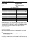
ORDERING INFORMATION
When purchasing replacement and modernization products from your TRADELINE® wholesaler or distributor, refer to the
TRADELINE® Catalog or price sheets for complete ordering number.
If you have additional questions, need further information, or would like to comment on our products or services, please write or
phone:
1. Your local Home and Building Control Sales Office (check white pages of your phone directory).
2. Home and Building Control Customer Relations
Honeywell, 1885 Douglas Drive North
Minneapolis, Minnesota 55422-4386
In Canada—Honeywell Limited/Honeywell Limitée, 35 Dynamic Drive, Scarborough, Ontario M1V 4Z9.
International Sales and Service Offices in all principal cities of the world. Manufacturing in Australia, Canada, Finland, France,
Germany, Japan, Mexico, Netherlands, Spain, Taiwan, United Kingdom, U.S.A.
SPECIFICATIONS
Model:
RM7895A
Electrical Ratings, see Table 1A:
Voltage and Frequency: 100 Vac (+10/-15%), 50 or 60 Hz
(+/- 10%).
1
Power Dissipation: RM7895: 10W maximum.
Maximum Total Connected Load: 2000 VA.
Fusing Total Connected Load: 20A maximum, type FRN or
equivalent.
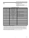
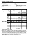
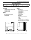
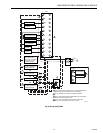
Table 1A. RM7895A Terminal Ratings.
1
Range of allowable operating frequency: 45 to 66 Hz.
2
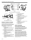
The 7895 must have an earth ground providing a connection between the subbase and the control panel or the equipment.
The earth ground wire must be capable of conducting the current to blow the 20A fuse (or breaker) in event of an internal short
circuit. The 7895 needs a low impedance ground connection to the equipment frame which, in turn, needs a low impedance
connection to earth ground. For a ground path to be low impedance at RF frequencies, the connection must be made with
minimum length conductors that have maximum surface areas. Wide straps or brackets rather than leadwires are preferred.
Be careful to verify that mechanically tightened joints along the ground path, such as pipe or conduit threads or surfaces held
together with fasteners, are free of nonconductive coatings and are protected against mating surface corrosion.
3
2000 VA maximum connected load to 7895 Assembly.
4
Can also be 100 Vac, 1A pilot duty.
5
Can also be 65 VA pilot duty with motorized valve, 1150 VA inrush, 460 VA open, 250 VA hold.
Terminal No. Description Ratings
G Flame Sensor Ground
Earth G Earth Ground
2
L2(N) Line Voltage Common
3 Alarm 100 Vac, 1A pilot duty.
4 Burner Motor 100 Vac, 9.8 AFL, 58.8 ALR (inrush).
5 Line Voltage Supply (L1) 100 Vac (+10/-15%), 50 or 60 Hz (+/- 10%).
3,4
6 Burner Controller and Limits 100 Vac, 1 mA.
7 Airflow Interlock 100 Vac, 9A.
8 Pilot Valve/Ignition 100 Vac, 4.5A ignition and 50VA pilot duty.
4
9 Main Fuel Valve 100 Vac, 2A pilot duty.
5
10 Ignition 100 Vac, 4.5A ignition.
4
F(11) Flame Sensor 60 to 220 Vac, current limited.
12 Unused
13 Unused
14 Unused
15 Unused
16 Unused
17 Unused
18 Unused
19 Unused
20 Unused
21 Unused
22 Shutter 100 Vac, 0.5A