


7800 SERIES EC7895A, RM7895A RELAY MODULE
65-0205
11
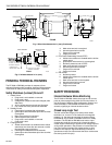
CONFIGURATION
JUMPERS
MICROCOMPUTER
RESET
PUSHBUTTON
RUN/TEST
SWITCH
STATUS LEDs
PLUG-IN PURGE
TIMER CARD
SAFETY RELAY
CIRCUIT
POWER SUPPLY
OPTIONAL KEYBOARD
DISPLAY MODULE
PLUG-IN
FLAME
AMPLIFIER
RELAY
DRIVE
CIRCUIT
CONTROL
POWER
TEST
JACK
REMOTE
RESET
DDL
DDL
COMMUNICATIONS
INDICATES FEEDBACK SENSING
OF RELAY CONTACT STATUS
AND LINE VOLTAGE INPUTS
FIELD WIRING
INTERNAL WIRING
IGNITION
PILOT
PILOT/V2
MAIN VALVE
1K
RELAY
STATUS
FEEDBACK
AND LINE
VOLTAGE
INPUTS
LIMITS CONTROLLER
LOCKOUT
INTERLOCK
1K1 2K1 5K1
FLAME SIGNAL
TEST
PROVIDE DISCONNECT MEANS AND OVERLOAD PROTECTION AS REQUIRED.
RM7895:,100VAC; EC7895: 200VAC.
RS485
1
2
3
5
L1
(HOT) L2
5
6
7
4K1
7K1
2K2
10
8
21
9
7K
6K
5K
4K
3K
2K
F
G
22
1
BLOWER
6K1
4
ALARM
3K1
3
L2
M11128
2
2
1
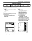
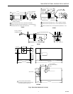
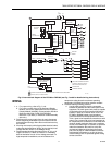
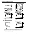
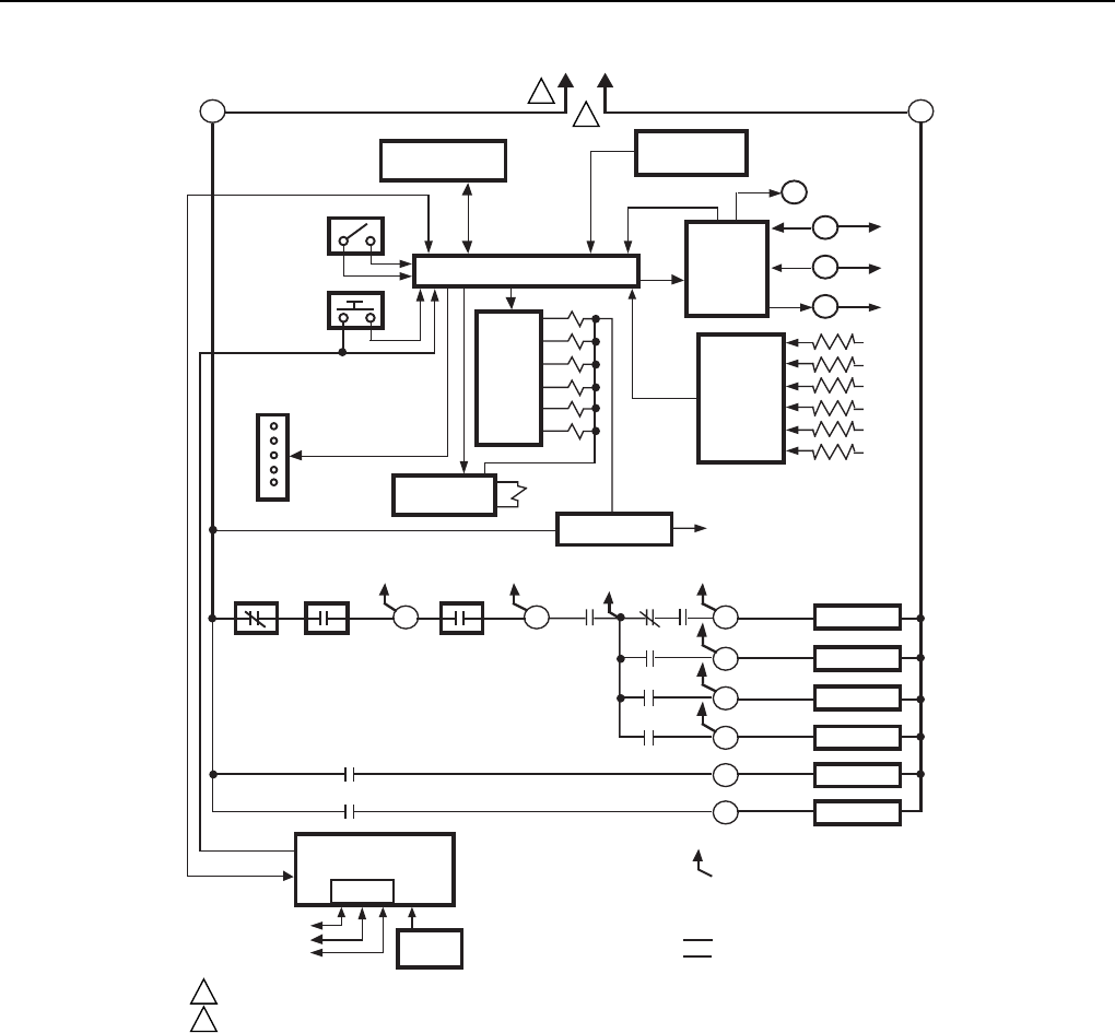
Fig. 6. Internal block diagram of the EC7895 or RM7895 (see Fig. 7 and 8 for detailed wiring instructions).
WIRING
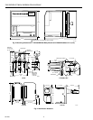
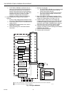
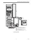
1. a. For proper wiring, refer to Fig. 7 or 8.
b. For proper remote wiring of the Keyboard Display
Module, refer to the Specifications for the Keyboard
Display Module (65-0090), Communication Interface
Base Unit (63-2278), DATA CONTROLBUS
MODULE™ (65-0091) or Extension Cable Assembly
(65-0131).
2. Disconnect the power supply from the main disconnect
before beginning installation to prevent electrical shock
and equipment damage. More than one disconnect may
be involved.
3. All wiring must comply with all appropriate electrical codes,
ordinances and regulations. Wiring, where required, must
comply with NEC Class 1 (Line Voltage) wiring.
4. Recommended wire size and type: use no. 14, 16, or 18
copper conductor (TTW60C or THW75C or THHN90C)
600 volt insulation wire for all Line Voltage terminals. For
high temperature installations, use wire selected for a
temperature rating above the maximum operating
temperature. All leadwires must be moisture resistant.
5. Recommended grounding practices:
a. Use the earth ground to provide a connection
between the subbase and the control panel or the
equipment. The earth ground wire must be capable
of conducting the current to blow the 20A fuse (or
breaker) in event of an internal short circuit. The
EC7895 or RM7895 needs a low impedance
ground connection to the equipment frame which,
in turn, needs a low impedance connection to earth
ground. For a ground path to be low impedance at
RF frequencies, the connection must be made with
minimum length conductors that have a maximum
surface area. Wide straps or brackets are preferred
rather than leadwires. Be careful to verify that
mechanically tightened joints along the ground
path, such as pipe or conduit threads or surfaces
held together with fasteners, are free of noncon-
ductive coatings and are protected against mating
surface corrosion.