


7800 SERIES EC7895A, RM7895A RELAY MODULE
65-0205
23
Initial Lightoff Check for Direct Spark Ignition
This check applies for gas and oil burners that do not use a
pilot. It should immediately follow the preliminary in-spection.
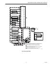
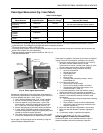
Refer to the appropriate sample block diagram of field wiring
for the ignition transformer and fuel valve(s) hookup.
NOTE: Low fuel pressure limits, if used, could be open. If
so, bypass them with jumpers during this check.
1. Open the master switch.
2. Complete the normal checkout of the fuel supply and
equipment as recommended by the equipment
manufacturer.
3. Close all manual main fuel shutoff valve(s). Check that
the automatic fuel valve(s) are closed. Make sure fuel is
not entering the combustion chamber.
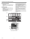
4. Close the master switch and start the system with a
call
for heat
by raising the set point of the operating
controller, see Fig. 15. The primary sequence should
start the ten-second INITIATE sequence.
5. Let the sequence advance through PREPURGE.
Ignition spark should occur after the PREPURGE
period. Listen for the click of the first stage fuel solenoid
valve(s).
6. Let the program sequence complete its cycle.
7. Open the manual fuel shutoff valve(s).
8. Reset the Lockout Switch and recycle the primary
sequence through PREPURGE.
9. Watch for the FLAME LED to help determine when the
first stage burner flame is established. If it is
established, proceed to step 15.
10. If the first stage burner flame is not established within
four seconds, or within the normal lightoff time specified
by the equipment manufacturer, close the manual fuel
shutoff valve(s), and open the master switch.
11. Check all burner adjustments.
12. Wait about three minutes. Close the master switch,
open the manual fuel shutoff valve(s), and try again to
lightoff the burner. The first attempt may have been
required to purge the lines and bring sufficient fuel to
the burner.
13. If the first stage burner flame is not established with-in
four seconds, or within the normal lightoff time specified
by the equipment manufacturer, close the manual fuel
shutoff valve(s) and open the master switch.
14. If necessary, repeat steps 8 through 13 to establish the
first stage burner flame. Then proceed to step 15.
15. When the first stage burner flame is established, the
sequence will advance to RUN. Make burner
adjustments for flame stability and input rating. If a
second stage is used, proceed to step 18.
16. Shut down the system by opening the burner switch or
by lowering the set point of the operating controller.
Make sure the burner flame goes out and make sure all
automatic fuel valve(s) close.
17. If used, remove the bypass jumpers from the low fuel
pressure limit and subbase.
18. If a second stage is used, make sure the automatic
second stage fuel valve(s) has opened and check the
light-off as follows. Otherwise proceed to step 19:
a. Open the manual second stage fuel valve(s).
b. Restart the system by raising the set point of the
operating controller.
c. When the first stage burner flame is established,
watch for the automatic second stage fuel
valve(s) to open. Observe that the second stage
lights off properly.
d. Make burner adjustments for flame stability and
input rating.
e. Shut down the system by lowering the set point of
the operating controller. Make sure the burner
flame goes out and all automatic fuel valve(s)
close.
19. Restart the system by closing the burner switch and/or
raising the set point of the operating controller. Observe
that the burner flame is established during PILOT IGN,
within the normal lightoff time specified by the
equipment manufacturer.
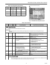
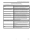
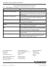
20. Measure the flame signal. Continue to check for the
proper signal, see Table 5, through the RUN period.
Any pulsating or unsteady readings require further
attention.
21. Make sure all readings are in the required ranges be-
fore proceeding.
NOTE: Upon completing these tests, open the master
switch and remove all test jumpers from the subbase
terminals, limits/control or switches.
22. Return the system to normal operation.
Pilot Turndown Test
(All Installations using a Pilot)
Perform this check on all installations that use a pilot. The
purpose of this test is to verify that the main burner can be lit
by the smallest pilot flame that will hold in the flame amplifier
and energize the FLAME LED. Clean the flame detector(s) to
make sure that it detects the smallest acceptable pilot flame.
If using AMPLI-CHECK® or Self-Checking Amplifier and 20K
ohm/voltmeter, the flame signal will fluctuate every time the
amplifier does a self-check or a shutter check.
NOTE: Low fuel pressure limits, if used, could be open. If
so, bypass them with jumpers during this test.
1. Open the master switch.
2. Close the manual main fuel shutoff valve(s).
3. Connect a manometer (or pressure gauge) to measure
pilot gas pressure during the turndown test.
4. Open the manual pilot shutoff valve(s).
5. Close the master switch and start the system with a
call
for heat
. Raise the set point of the operating controller.
The primary sequence should start and PREPURGE
should begin.
6. INTERMITTENT PILOT MODELS—After the sequence
has entered the normal burner run period, turn down
pilot gas pressure very slowly, reading the manometer
(or gauge) as the pressure drops. Stop immediately
when the FLAME LED goes out. Note the pressure at
this point.
a. If the Flame Failure Action jumper
is not clipped
,
allow the EC7895 or RM7895A to recycle through
PREPURGE. If the Flame Failure Action jumper
is clipped
, push the reset pushbutton and allow
the EC7895 or RM7895A to recycle through
PREPURGE.
b. As the control attempts to relight the pilot, turn
the pilot gas pressure back up slowly until the
FLAME LED comes on. This step must be
completed within 4 or 10 seconds, depending on
the selected PFEP, or lockout will occur.