


7800 SERIES EC7895A, RM7895A RELAY MODULE
65-0205
26
TROUBLESHOOTING
EC7895 or RM7895 System Diagnostics
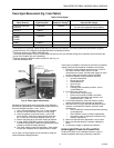
Troubleshooting control system equipment failures is easier
with the 7895 self-diagnostics and first-out annunciation. In
addition to an isolated spst alarm relay (audible annunciation),
the 7895 provides visual annunciation by displaying the
ALARM LED.
Self-diagnostics of the 7895 enable it to detect and annunciate
both external and internal system problems. Ex-ternal faults
such as interlock failures, flame failures and false flame signals
are annunciated by the 7895, which energizes the ALARM LED
or by using the optional Keyboard Display Module. The 7800
SERIES provides a System Annunciation Diagnostics and
Troubleshooting manual, form 65-0118.
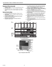
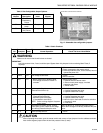
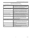
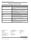
The 7895 provides diagnostic information to aid the service
mechanic to obtain information when troubleshooting the
system, see Table 6.
The optional Keyboard Display Module displays sequence
status messages indicating: STANDBY, PRE-PURGE, PILOT
IGN, MAIN IGN and RUN. The selectable messages also
provide visual indication, current status and historical status
of the equipment such as: Flame Signal, Total Cycles, Total
Hours, Fault History, and Diagnostic Information. With this
information most problems can be diagnosed without
extensive trial and error testing. Information available in the
Diagnostic Information file includes: Device Type, Device
Suffix, Software Revision, Manufacturing Code, Flame
Amplifier Type, Flame Failure Response Time, Selectable
Jumper Configuration Status, and Terminal Status.
Diagnostic Information Index
The EC7895 or RM7895 with the optional Keyboard Display
Module can monitor input/output terminals and can display
the status of the terminal at the VFD (example; Pilot Valve T8
ON<), see S7800A Keyboard Display Module Specifications.
A complete terminal description and number are provided.
The display will show the actual status of the terminal. If
voltage is detected at the terminal, ON is displayed; but if no
voltage is detected at the terminal, OFF is displayed.
Historical Information Index
The EC7895 or RM7895 has nonvolatile memory that allows
the Relay Module to retain Historical Information for the six
most recent lockouts. Each of the six lockout files retains the
cycle when the fault occurred, the hour of operation when the
fault occurred, and the fault message and burner status when
the fault occurred. The Historical Information can be viewed
by the optional S7800A Keyboard Display Module
Specifications.
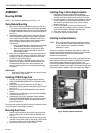
SERVICE NOTE: A Lockout condition or restart of a EC7895
or RM7895 can be accomplished by
pressing the reset push-button on the
EC7895 or RM7895, or by pressing a
remote reset pushbutton wired through an
optional Keyboard Display Module, DATA
CONTROLBUS MODULE™, Extension
Cable Assembly or Remote Reset Module.
A power-up reset causes an electrical reset
of the EC7895 or RM7895 but does not
reset a lockout condition.
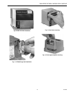
SERVICE NOTE: Remove the access slot covers on the
sides of the Q7800A,B to check voltages.
CAUTION
Reinstall access slot covers on the Q7800A,B
Subbase after performing voltage checks.
SERVICE NOTE: Maximum ambient operating temperature
of a C7012E,F Series 1 through 6 is
reduced to 125° F because of the duty
cycle operation of the 7895 Relay Module.