


7800 SERIES EC7895A, RM7895A RELAY MODULE
65-0205
17
OPERATION
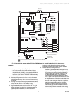
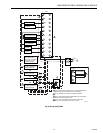
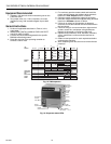
Sequence of Operation
The EC7895 or RM7895 has the following operating
sequences, see Fig. 15.
Initiate
The EC7895 or RM7895 enters the INITIATE sequence when
the Relay Module is powered. The EC7895 or RM7895 can
also enter the INITIATE sequence if the Relay Module verifies
voltage fluctuations of +10/-15% or frequency fluctuations of
+/- 10% during any part of the operating sequence. The
INITIATE sequence lasts for ten seconds unless the voltage
or frequency tolerances are not met. When the tolerances are
not met, a hold condition is initiated and is displayed on the
optional VFD for at least five seconds. When the tolerances
are met, the INITIATE sequence restarts. If the condition is
not corrected and the hold condition exists for four minutes,
the RM7895 locks out. Causes for hold conditions in the
INITIATE sequence are:
• AC line dropout is detected.
•AC line noise that can prevent a sufficient reading of the
line voltage inputs.
• Brownouts caused by a low line voltage.
The INITIATE sequence also delays the burner motor starter
from being energized and de-energized from an intermittent
AC line input or control input.
Standby
The EC7895 or RM7895 is ready to start an operating
sequence when the operating control input determines a
call
for heat
is present. The burner switch, limits, operating limit
control and all microcomputer monitored circuits must be in
the correct state for the EC7895 or RM7895 to continue into
the PRE-PURGE sequence.
Normal Start-Up Prepurge
The EC7895 or RM7895 provides a selectable PREPURGE
timing from two seconds to 30 minutes with power applied
and the EC7895 or RM7895 operating control indicating a
call
for heat
.
a. Airflow Interlock, burner switch, and all microcomputer
monitored circuits must be in the correct operating state.
b. The blower motor output, terminal 4, is powered to start
the PREPURGE sequence.
c. The Airflow Interlock input must close ten seconds into
PREPURGE or within the specified purge card timing;
otherwise, a recycle to the beginning of PRE-PURGE
or lockout occurs depending on how the airflow switch
selectable jumper is configured.
Ignition Trials
a. Pilot Flame Establishing Period (PFEP):
1. The pilot valve and ignition transformer, terminals 8
and 10, are energized. The EC7895 or RM7895A
has an intermittent pilot valve, terminal 8.
2. Flame must be proven by the end of the 4 or 10
sec-ond PFEP to allow the sequence to continue.
If flame is not proven by the end of PFEP, a
safety shutdown occurs.
3. At the end of PFEP, the ignition, terminal 10, is
de-energized.
b. Main Flame Establishing Period (MFEP):
1. After the Ignition Trials, and with the presence of
flame, the main fuel valve, terminal 9, is powered.
If a flameout occurs, the EC7895A or RM7895A
will lock out or recycle within .8 or 3 seconds,
depending on the Flame Failure Response Time
(FFRT) of the amplifier.
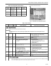
Run
1. The EC7895A or RM7895 is now in RUN and remains
in RUN until the controller input, terminal 6, opens,
indicating that the demand is satisfied or a limit opened.
See Table 6 for further details of Hold conditions.
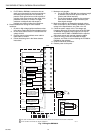
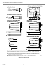
Selectable Site-Configurable Jumpers
The EC7895 or RM7895 has three site-configurable jumper
options, see Fig. 17 and Table 3. The site-configurable
jumpers should be clipped with side cutters and the resistors
removed from the Relay Module.
SERVICE NOTE: Clipping and removing a site-configurable
jumper enhances the level of safety.
Static Checkout
CAUTION
1. Use extreme care while testing the system. Line
voltage is present on most terminal connections
when power is on.
2. Open the master switch before installing or
removing a jumper on the subbase.
3. Before continuing to the next test, be sure to re-
move test jumper(s) used in the previous tests.
4. Replace all limits and interlocks not operating
properly. Do not bypass limits and interlocks.
5. Close all manual fuel shutoff valve(s) before
starting these tests.
After checking all wiring, perform this checkout before
installing the EC7895 or RM7895 on the subbase. These
tests verify the Q7800 Wiring Subbase is wired correctly, and
that the exter-nal controllers, limits, interlocks, actuators,
valves, transformers, motors and other devices are operating
properly.
NOTE: Do not perform a dielectric test with the EC7895 or
RM7895 installed. Internal surge protectors will
break down and conduct a current. This could cause
the EC7895 or RM7895 to fail the dielectric test or
possibly destroy the internal lightning and high
current transient protection components.