


7800 SERIES EC7895A, RM7895A RELAY MODULE
65-0205
19
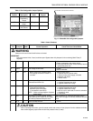
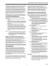
Table 3. Site Configurable Jumper Options.
Jumper
Number Description Intact Clipped
JR1 Pilot Flame
Establishing
Period
10 seconds 4 seconds
JR2 Flame Failure
Action
Recycle Lockout
JR3 Airflow Switch
(ILK) Failure
Recycle Lockout
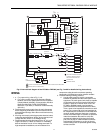
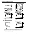
Fig. 17. Selectable site-configurable jumpers.
SELECTABLE CONFIGURATION JUMPERS
M11126
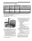
Table 4. Static Checkout.
Test
No.
Test
Jumpers
Volt-
meter Normal Operation
If Operation Is Abnormal,
Check The Items Listed Below
WARNING
Make sure all manual fuel shutoff valves are closed.
IMPORTANT
Low fuel pressure limits, if used, could be open. Bypass them with jumpers for the remaining Static Tests (if
required).
1 None 5-L2 Line voltage at terminal 5. 1. Master switch.
2. Power connected to the master switch.
3. Overload protection (fuse, circuit breaker) has not
opened the power line.
2 None 6-L2 Line voltage at terminal 6. 1. Limits.
2. Burner controller.
3 4-5 7-L2 1. Burner motor (fan or blower) starts.
2. Line voltage at terminal 7 within 10
seconds.
1. Burner motor circuit.
a. Manual switch of burner motor.
b. Burner motor power supply, overload
protection and starter.
c. Burner motor.
4 5-10 — Ignition spark (if ignition transformer is
connected to terminal 10).
1. Watch for spark or listen for buzz.
a. Ignition electrodes are clean.
b. Ignition transformer is okay.
5 5-8 — 1. Ignition spark (if ignition transformer is
connected to terminal 8).
2. Automatic pilot valve opens
(if connected to terminal 8).
NOTE: Refer to wiring diagram of system
being tested.
1. Watch for spark or listen for buzz.
a. Ignition electrodes are clean.
b. Ignition transformer is okay.
2. Listen for click or feel head of valve for activation.
a. Actuator if used.
b. Pilot valve.
6 5-9 — Automatic fuel valve(s) opens. If using
direct spark ignition, check the first stage
fuel valve(s) instead of the pilot valve.
Same as test no. 6. If using direct spark ignition,
check the first stage fuel valve(s) instead of the pilot
valve.
75 -3 — Alarm (if used) turns on. 1. Alarm
Final
CAUTION
After completing these tests, open the master switch and remove all test jumpers from the subbase terminals.
Also remove bypass jumpers from the low fuel pressure limits (if used).