


7800 SERIES EC7895A, RM7895A RELAY MODULE
65-0205
12
b. For EC7895 or RM7895, each device has an
earth ground terminal that must be grounded to
the metal control panel with wire as short as
practical. Each ground wire must be capable of
carrying a fault current equal to the rating of the
protective fuse (20A). A number 14 copper
conductor is adequate but wide straps or
brackets are preferred rather than leadwires.
6. Recommended wire routing for flame detector
leadwires:
1. Do not run high voltage ignition transformer wires
in the same conduit with the flame detection wiring.
2. Do not route scanner wires in a conduit with line
voltage circuits.
3. Enclose scanner wires without armor cable in
metal cable or conduit.
4. Follow directions given in the flame detector
Instructions.
7. Maximum wire lengths:
a. For the EC7895 or RM7895, the maximum length
of leadwire to the terminal inputs is 300 feet
(Control and Airflow Interlock).
b. For the flame detector leadwires, the maximum
flame sensor leadwire length is limited by the
flame signal strength.
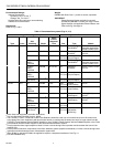
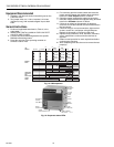
8. Make sure loads do not exceed the terminal ratings.
Refer to the label on the EC7895 or RM7895 or to the
ratings in the Specifications, see Table 1A or 1B.
9. Check the power supply circuit. The voltage and
frequency tolerance must match those of the EC7895
or RM7895. A separate power supply circuit may be
required for the EC7895 or RM7895 with the required
disconnect means and overload protection added.
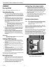
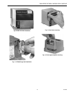
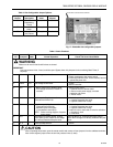
10. Check all wiring circuits and complete the Static
Checkout, see Table 4, before installing the EC7895 or
RM7895 on the subbase.
11. Install all electrical connectors.
12. Restore power to the panel.
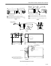
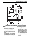
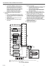
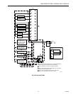
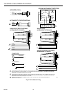
Fig. 7. Wiring the RM7895A.
M5111A
G
L2
3
5
6
7
8
9
10
F
(L1)
13
14
15
16
17
18
19
20
21
22
12
MASTER
SWITCH
IGNITION
MAIN FUEL
VALVE(S)
BURNER
CONTROLLER/LIMITS
BURNER MOTOR
(BLOWER)
INTERMITTENT
PILOT/IGNITION
RECTIFYING FLAME
ROD, RECTIFYING
PHOTOCELL, OR INFRA-
RED (LEAD SULFIDE)
FLAME DETECTOR
120V, 50/60 Hz POWER SUPPLY. PROVIDE DISCONNECT MEANS AND OVERLOAD PROTECTION AS REQUIRED.
DO NOT CONNECT ANY WIRES TO UNUSED TERMINALS.
FOR DIRECT SPARK IGNITION
(OIL OR GAS)
100V ALARM
L1
(HOT)
L2
1
L2
WHITE
WHITE
WHITE
BLACK
BLACK
L1
L2
9
8
10
IGNITION
TRANSFORMER
MAIN VALVE
1
Q7800
2
2
L2
4
AIRFLOW
INTERLOCK
OR
OR
YELLOW
BLUE
BLUE
C7027A, C7035A, OR
C7044A ULTRAVIOLET
FLAME DETECTOR
C7012A,C,E,F OR
C7076A,D ULTRAVIOLET
FLAME DETECTOR