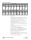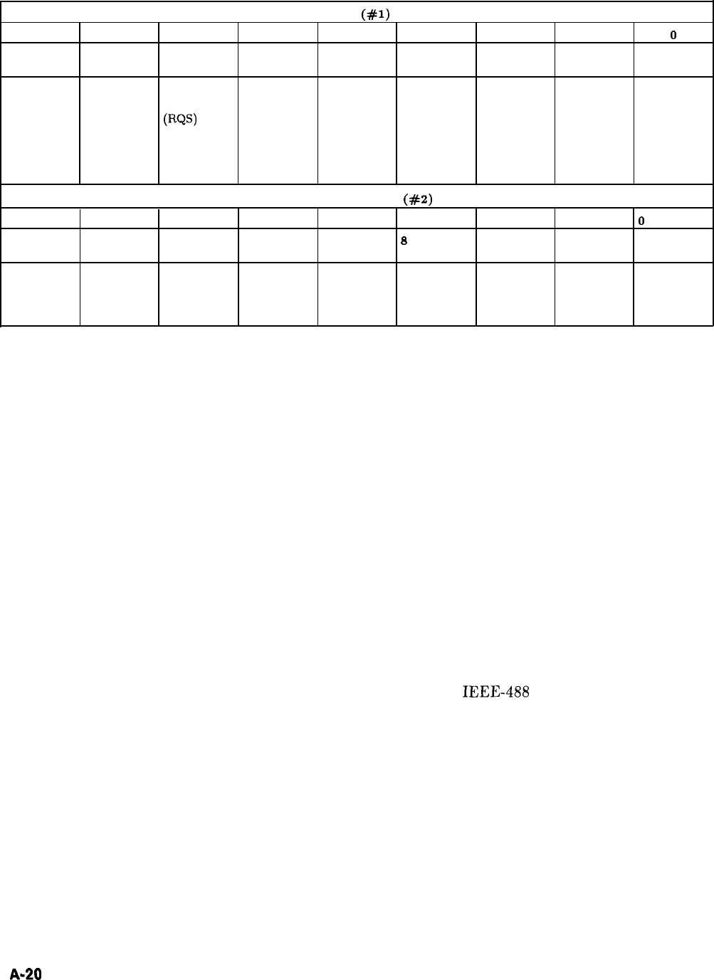
ANALYZER STATUS REGISTER
STATUS BYTE
(#l)
Bit #
7
6 5
4
3 2
1
0
Decimal
128
64 32
16
8
4
2
1
Value
Function
SRQ on new REQUEST SRQ on SRQ on
SRQ on
SRQ on
SRQ on SRQ on
frequencies
SERVICE HP-IB or End of
RF Settled
Changed in
Numeric
Any Front
or sweep
(RQS)
syntax error. Sweep
Extended Entry Panel Key
time in
status
Completed
Pressed
effect.
Byte (HP-IB or
Front
Panel)
EXTENDED STATUS BYTE
(#2)
Bit #
7
6 5
4
3 2
1
0
Decimal
128
64
32
6
a
4
2
1
Value
Function
Fault
RF Unleveled Power
RF Unlocked External Oven
Over
Self Test
Indicator Failure
Frequency
Cold Modulation
Failed
On
Reference
Selected
Status Byte 1
Bit 0: SRQ caused by a key closure on the front panel of the
synthesizer (use the OM code to determine the front panel status).
Bit 1: SRQ caused by the completion of a numeric entry (use the OA
code to determine the value of the numerical entry).
Bit 2: SRQ caused by a change in the extended status byte (status
byte 2) affected by the RE-coded mask (see the RE code for an
explanation of this masking).
Bit 3: SRQ caused by the completion of phase locking and the
settling of the RF source (use the OK code to determine the last lock
frequency).
Bit 4: SRQ on end-of-sweep or mid-sweep update in NA (network
analyzer code) mode.
Bit 5: SRQ caused by HP-IB syntax error.
Bit 6: SERVICE REQUEST; by
IEEE-488
convention, the
instrument needs service from the controller when this bit is set true.
Bit 7: SRQ caused by a change in the coupled parameters (start
frequency, center frequency, and sweep time). Use the OC code to
determine the new values of the coupled parameters.
Status Byte 2 (Extended Status Byte)
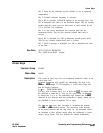
Bit 0: Self test failed at power on or at Instrument Preset. This bit
remains latched until this status byte has been read, or until cleared
by the CS or CLEAR 719 commands.
Bit 1: Excessive amplitude modulation input.
A-20
Operating and Programming Reference
HP 8360
User’s Handbook


