


Technician repair removal and replacement procedures 117
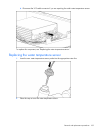
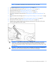
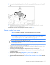
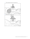
12. Disconnect the threaded pick-up at the top of the flow meter and pull the flow meter out of the MCS
unit.
13. Remove the threaded pick-up and cable from the MCS unit, and disconnect from the connector
labeled X14 on the water group controller.
To replace this component, see "Replacing the flow meter (on page 117)."
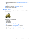
Replacing the flow meter
NOTE: This procedure is specifically for the replacement of the Type 2 flow meter.
NOTE: The Type 2 flow meter should arrive with the paddle-wheel sensor already installed in
the top of the flow meter. For information concerning the installation of the paddle-wheel
sensor, see Replacing the flow meter paddle-wheel sensor (on page 57).
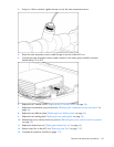
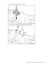
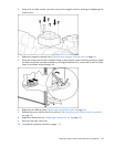
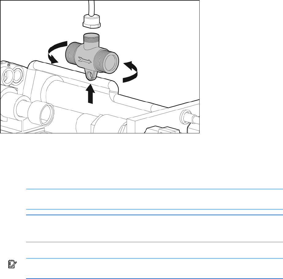
1. Insert the two fiber gaskets on either side of the flow meter.
IMPORTANT: Be sure the arrow on the flow meter is pointing toward the rear of the MCS unit
to ensure proper water flow.
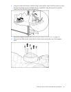
2. Insert the flow meter back into place on the water line.
3. Using the 46-mm wrench (included in the miscellaneous hardware kit), tighten the two union nuts to
secure the flow meter to the water line.
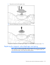
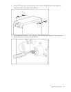
4. Route the flow meter paddle-wheel sensor cable through to the front of the MCS unit.
5. Connect the flow meter paddle-wheel sensor cable connector to the connector labeled X14 on the
water group controller.
6. Replace the AC transfer switch ("Replacing the AC transfer switch" on page 28).
7. Replace the magnetic solenoid valve ("Replacing the magnetic solenoid valve" on page 84).
8. Replace the bottom heat exchanger unit ("Replacing the heat exchanger unit with couplers" on page
63).