


55
Heat & Glo • 550TRSI-AUF, 550TRSILP-AUF • 2079-980 Rev. N • 5/12
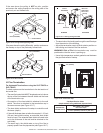
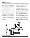
BLUE
BROWN
GREEN/
YELLOW
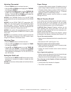
Figure 12.2
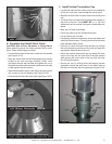
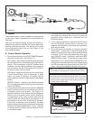
D. Blower
These heaters have a factory installed fan and electrical
junction cord. These components are located behind the
lower door.
Use of the fan requires that the Junction cord (factory in-
stalled) be connected to 220/240 VAC service before per-
manently enclosing the heater. The service cord is found
on the right exterior side of the unit. See Figure 12.2 for
wire connection detail.
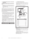
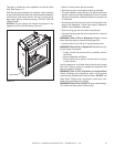
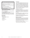
E. Control Module Operation
1. The control module has an ON/OFF/REMOTE selector
switch that must be set. See Figure 12.3.
OFF Position: Appliance will ignore all power inputs and
will not respond to any commands from a wall switch or
remote. The unit should be in the OFF position during
installation, service, battery installation, fuel conversion,
and in the event that the control goes into LOCK-OUT
mode as a result of an error code.
ON Position: Appliance will ignite and run continuously
in the HI ame setting, with no adjustment in ame
output. This mode of operation is primarily used for
initial installation or power outage operation with battery
backup.
REMOTE Position: Appliance will initiate commands
from an optional wired wall switch and/or the wireless
remote (RC300AU).
2. If using a wired wall switch with the module in REMOTE
mode, the ame output can be adjusted with the HI/
LO selector switch on the module. See Figure 12.3.
Note that the ame HI/LO selector switch will become
inactive once an optional remote control (RC300AU)
is programmed to the control module. Note that the
control module will always ignite the replace on HI
and remain so for the initial 10 seconds of operation.
If the HI/LO is switched to the LO position, the ame
output will automatically drop to the lowest setting after
the ame has been established for 10 sec. After this
10 second period, the ame can be adjusted from HI
to LO with the switch.
3. The control module has safety feature that automatically
shuts down the replace after 9 hours of continuous
operation without receiving a command from the
RC300AU remote.
4. If you intend to use both an optional wired wall switch
and the RC300AU remote control to operate your
replace, the wall switch will override any commands
given by the remote.
5. The module has the capability to recognize potential
malfunctions. If these occur, it will fail to ignite and/or
respond to a command to ignite via the wall switch and/
or remote. In this case, the module may have gone
into LOCK-OUT mode. In this state, it will emit a RED/
GREEN LED error code. To reset the error code, switch
the selector to OFF, and then back to REMOTE or ON.
If the ignition command again fails, the module will emit
an LED error code, prior to going back into LOCK-OUT
mode. Contact your dealer for service if this occurs.
Note: If the module is in LOCK-OUT mode, resetting the
circuit breaker to the appliance will also reset the module.
Note: For units installed in Australia, the residence’s 220/240
wall outlet to which this appliance’s power cord is connected,
must be wired to an in-line on/off switch. This is required for
servicing and/or resetting the control module in the event of
a control module LOCK-OUT.
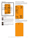
Figure 12.3 Control Module
NG/LP SETTING
STATUS INDICATOR LED
SELECTOR
SWITCH
FLAME HI/LO SWITCH