


23
Heat & Glo • 550TRSI-AUF, 550TRSILP-AUF • 2079-980 Rev. N • 5/12
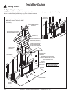
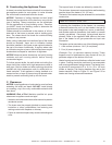
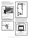
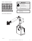
D. Mantel and Wall Projections
WARNING!RiskofFire!Comply with all minimum clear-
ances as specied. Framing or nishing material closer than
the minimums listed must be constructed entirely of noncom-
bustible materials (i.e., steel studs, concrete board, etc).
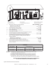
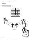
Combustible Mantels
Combustible Mantel Legs or Wall Projections
Note: All measurements in millimeters.
Note: Measurement is taken from top of the opening,
NOT the top of the replace.
Figure 5.4 Clearances to Mantel Legs or Wall Projections
(Acceptable on both sides of opening.)
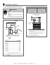
Figure 5.3 Minimum Vertical and Maximum Horizontal
Dimensions of Combustibles
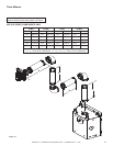
Figure 5.3 Non-combustible zone
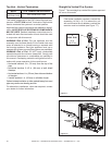
Figure 5.4
76
152
178
203
229
279
305
51
76
102
127
305
279
254
229
203
178
152
51
102
127
254
TOP FRONT EDGE
OF FIREPLACE
NON-COMBUSTIBLE
BOARD
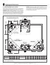
If joints between the nished walls and the heater surround
(top and sides) are sealed, a 149 ºC (300 ºF) minimum seal-
ant material must be used. These joints are not required to
be sealed. Only non-combustible material (using 149 °C
(300 ºF). minimum adhesive, if needed) can be applied as
facing to the heater surround. See Figure 5.4.
FINISH WALL MATERIAL MAY BE
COMBUSTIBLE - TOP AND SIDES
NON-COMBUSTIBLE
BOARD
HIGH TEMPERATURE (149 ºC (300 ºF) MIN.)
TOP AND SIDE SEAL JOINT
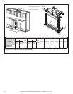
Note: Zero clearance nishing allowed on sides of surround
and top of non-combustible board.
1/2 in. (13 mm)
SHEETROCK
3-1/2 in.
(89 mm)
1/2 in.
(13 mm)
NON-COMBUSTIBLE ZONE
NON-COMBUSTIBLE
BOARD SHIPPED
WITH APPLIANCE
3 ft. (914 mm) MAXIMUM
TOP VIEW
2-7/8 in.*
(73 mm)
MINIMUM
1/2 in.
*
(13 mm)
MINIMUM
* Add 1/2 in. (13 mm for rear vent)