


25
Heat & Glo • 550TRSI-AUF, 550TRSILP-AUF • 2079-980 Rev. N • 5/12
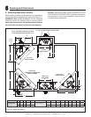
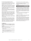
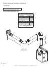
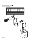
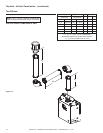
Figure 6.3 Minimum Clearances for Termination
NOTES: 1. All distances are measured vertically or horizontally along the wall to a point
in line with the nearest part of the terminal.
2. Prohibited area below electricity meter or fuse box extends to ground level.
3. See clause 5.13.6.6 for restrictions on a ue terminal under a roofed area.
4. See Appendix J, Figure J1(a) and J2(a) for clearances required from a ue
terminal to a LP Gas cylinder. A ue terminal is considered to be a source of ignition.
MINIMUM CLEARANCES REQUIRED FOR BALANCED FLUE TERMINALS
OR THE FLUE TERMINALS OF OUTDOOR APPLIANCES
T = Flue terminal M = Gas meter Shading indicates prohibited
I = Mechanical air inlet P = Electricity meter or fuse box areas for ue terminals
f
c
n
I
openable
window
j
jj
door
h
h
h
T
e e
P
T
g
k
k
d
b
d
M
a
c
g
See note 2
See note 3
T
a - Below eaves, balconies or other projections: MIN. CLEARANCE - in. (mm)
Appliances up to 50 MJ/h input .................................................................................... 12 (300)
Appliances over 50 MJ/h input ...............................................................................20-1/2 (500)
b - From the ground or above a balcony ............................................................................... 12 (300)
c - From a return wall or external corner .........................................................................20-1/2 (500)
d - From a gas meter (M) ...................................................................................................... 39 (1000)
e - From an electricity meter or fuse box (P) ...................................................................20-1/2 (500)
f - From a drain or soil pipe .................................................................................................... 6 (150)
g - Horizontally from any building structure (unless appliance approved
for closer installation) or obstruction facing a terminal ...............................................20-1/2 (500)
h - From any other ue terminal, cowl, or combustion air intake ....................................20-1/2 (500)
j - Horizontally from an openable window, door, non-mechanical air
inlet, or any other opening into a building, with the exception of
sub-oor ventilation:
Appliances up to 150 MJ/h input ............................................................................20-1/2 (500)
Appliances over 150 MJ/h input ................................................................................... 60 (1500)
k - From a mechanical air inlet, including a spa blower ....................................................... 60 (1500)
n - Vertically below an openable window, non-mechanical air
inlet or any other opening into a building, with the exception of ...................................... See table
sub-oor ventilation ................................................................................................................ below
CLEARANCE
Space Heaters All other appliances
Up to 50 MJ/h input Up to 50 MJ/h input
Over 50 MJ/h input and
Up to 150 MJ/h input
Over 50 MJ/h input
6 in. (150 mm) 20 in. (500 mm) 39 in. (1000 mm) 59 in. (1500 mm)