


21
Heat & Glo • 550TRSI-AUF, 550TRSILP-AUF • 2079-980 Rev. N • 5/12
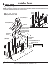
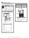
B. Constructing the Appliance Chase
A chase is a vertical box-like structure built to enclose the
gas appliance and/or its vent system. In cooler climates
the vent should be enclosed inside the chase.
NOTICE:Treatment of ceiling restops and wall shield
restops and construction of the chase may vary with the
type of building. These instructions are not substitutes
for the requirements of local building codes. Therefore,
you MUST check local building codes to determine the
requirements to these steps.
Chases should be constructed in the manner of all out-
side walls of the home to prevent cold air drafting prob-
lems. The chase should not break the outside building
envelope in any manner.
Walls, ceiling, base plate and cantilever oor of the chase
should be insulated. Vapor and air inltration barriers
should be installed in the chase as per regional codes for
the rest of the home. Additionally, in regions where cold
air inltration may be an issue, the inside surfaces may be
sheetrocked and taped for maximum air tightness.
NOTICE:Measure heater dimensions and verify framing
methods and wall covering details, before framing
construction begins.
To further prevent drafts, the wall shield and ceiling re-
stops should be caulked with high temperature caulk to
seal gaps. Gas line holes and other openings should be
caulked with high temperature caulk or stuffed with un-
faced insulation. If the appliance is being installed on a
cement surface, a layer of plywood may be placed under-
neath to prevent conducting cold up into the room.
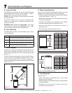
C. Clearances
NOTICE:Install appliance on hard metal or wood surfaces
extending full width and depth. DO NOT install directly
on carpeting, vinyl, tile or any combustible material other
than wood.
WARNING! Risk of Fire! Maintain specied air space
clearances to appliance and vent pipe:
• Insulation and other materials must be secured to prevent
accidental contact.
• The chase must be properly blocked to prevent blown
insulation or other combustibles from entering and
making contact with replace or chimney.
• Failure to maintain airspace may cause overheating and
a re.
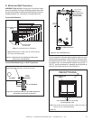
The top and back of heater are dened by stand-offs.
The minimum clearance to a perpendicular wall extending
past the face of the heater is 1in. (25 mm).
The back of the heaters may be recessed into combustible
construction.
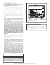
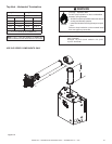
In planning the installation for the heater it is necessary
to determine where the unit is to be installed, the type of
ue system to be used (straight out, corner, or elevated),
and whether optional accessories (wall switch or remote
control) are desired. Gas supply piping should also be
planned. Refer to the appliance data plate on the base
pan of the heater for all gas pressures and input rate
information.
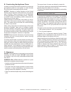
The heater can be mounted on any of the following surface:
1. A at surface (minimum 1/4 in. (6 mm) base).
2. Four (4) corner supports.
(Example: Four (4) concrete masonry blocks). These
supports must be positioned so they contact all four (4)
perimeter edges on the bottom of the unit.
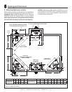
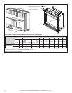
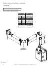
Heater framing can be built before or after the heater is set
in place. Framing should be positioned to accommodate
wall covering and heater facing material. The heater fram-
ing should be constructed of 2 in. X 4 in. (51 x 102 mm)
lumber or heavier. The framing headers may rest on the
heater standoffs. Refer to Figure 5.1 and Figure 5.3 for
heater and framing reference dimensions.
Note: Not intended for heater insert.