


49
Heat & Glo • 550TRSI-AUF, 550TRSILP-AUF • 2079-980 Rev. N • 5/12
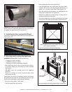
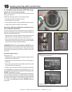
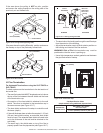
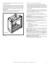
Figure 10.15 Ceiling Firestop (Ceiling Side)
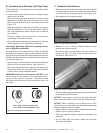
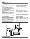
Figure 10.16 Attic Firestop
CEILING
CEILING FIRESTOP
RAFTER
NAILS (4 REQUIRED)
JOIST
CEILING FIRESTOP
CEILING
NAILS (4 REQUIRED)
If the area above the ceiling IS an attic, position and secure
the restop on top of the previously framed hole.
If the area above the ceiling is NOT an attic, position
and secure the ceiling restop on the ceiling side of the
previously cut and framed hole.
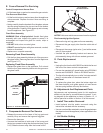
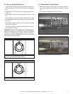
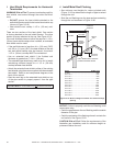
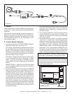
Figure 10.17 Venting through the Wall
• The termination kit should pass through the wall restops
from the exterior of the building.
• Adjust the termination cap to its nal exterior position on
the building and interlock the ue sections.
WARNING!RiskofFire!the termination cap must be
positioned so that the arrow is pointing up.
• Use a high-temperature sealant gasket to seal between
the pipe and exterior restop.
EXTERIOR
INTERIOR
Interior
Wall Shield
Inner Flue
Rear Flue
Heat Shield
38 mm min.
overlap
Outer Flue
H. Flue Termination
For Horizontal Terminations using the SLP-TRAP2 or
DVP-TRAP2
To attach and secure the termination to the last section of
horizontal ue:
• The rear ue heat shield MUST be placed one inch above
the top of the ue between the wall shield and the base
of the termination cap.
• One section of the heat shield is attached to the wall
shield. The other is attached to the termination cap in
the same manner (see Figure 10.17).
• The heat shield sections will overlap to match the wall
thickness (depth).
• If the wall thickness does not allow the required 1-1/2 inch
(38 mm) heat shield overlap, an extended heat shield
must be used. The extended heat shield will need to be
cut to the thickness of the wall and be attached to the
wall shield.
• The small leg in the shield rests on top of the ue to
properly space it from the pipe section (see Figure 10.17).
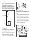
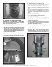
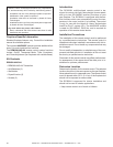
Figure 10.18 Termination Cap
1 in. (25 mm)
7-1/2 in.
(192 mm)
MINIMUM
Cap Specication Chart
(depth without using additional pipe sections)
550TRSI-AUF
550TRSILP-AUF
DVP-TRAP2 / SLP-TRAP2
Rear Vent Depth
5-1/2 in. (152 mm) to 9-1/2 in. (241 mm)