


Heat & Glo • 550TRSI-AUF, 550TRSILP-AUF • 2079-980 Rev. N • 5/12
44
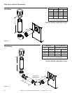
Natural Gas Propane Butane
550TRSI-AUF 11.13 mm N/A N/A
550TRSILP-AUF N/A Full Open Full Open
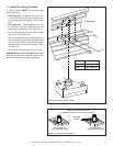
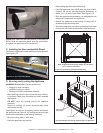
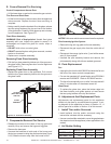
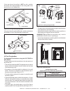
Figure 9.17 Fixed Glass Assembly
GLASS
ASSEMBLY
LATCHES
(BOTH BOTTOM
AND TOP)
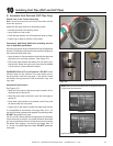
E. Covers Removal For Servicing
Control Compartment Access Door
• Lift the lower door up and out to access the gas controls.
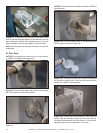
Trim Door and Glass Door
• Lift the front trim door up and out away from the appliance
side surrounds. Replace the door when servicing is
complete.
• Noting carefully how the brackets t on the glass, release
the two spring latches at the top and two at the bottom
of the glass door. Carefully lift the glass up and out away
from the appliance. See Figure 9.17.
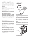
Pilot Assembly/Ignition System
• Remove the log set, log grate and burner assembly.
• Disconnect the gas supply tube from the outlet side of
valve.
• Disconnect the orange ignitor wire (I) and white sensor
wire (S) from module.
• Unscrew the pilot assembly bracket and remove, the
pilot assembly along with silicone sealant grommet.
G. Parts Replacement
Fan
• Unplug the fan from the AUX300CE and slide the fan out
the front of the lower controls compartment.
• Fan can be operated at 3 speed levels using RC300AU
remote and AUX300CE. Refer to RC300AU section.
• The fan will automatically turn on after 3 minutes and will
stop 12 minutes after unit has been turned off.
Glass Panel
• To replace the glass door, place the bottom edge into
the lower holders, push glass against unit and secure
the two spring latches at the top and bottom.
H. Adjustments And Replacement Parts
Adjustments and replacement parts for this appliance
should only be done by a qualied service person. A wir-
ing diagram for the appliance is shown in Section 12. A
service parts list is shown in Section 16 of this manual.
I. Install Trim and/or Surround
• Install optional trim kits and/or surrounds using the
instructions included with the accessory.
• Use non-combustible materials to cover the gap between
the sheet rock and the appliance (when applicable to the
model).
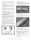
J. Air Shutter Setting
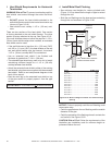
Figure 9.18
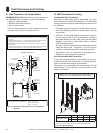
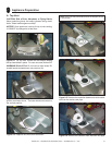
F. Components Removal For Service
• Release the screws at the base of the log grate and
carefully lift up and remove the logs and log grate.
• Remove the base pan.
• Unscrew the brackets at both ends of the burner and
the top two screws locating the pilot bracket (see Figure
9.18). Slide the burner away from the burner orice.
NOTICE:All screws which were removed must be replaced.
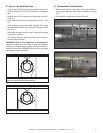
PILOT BRACKET
RETAINING SCREWS
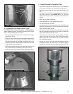
Fixed Glass Assembly
WARNING! Risk ofAsphyxiation! Handle xed glass
assembly with care. Inspect the gasket to ensure it is
undamaged and inspect the glass for cracks, chips or
scratches.
• DONOT strike, slam or scratch glass.
• DONOT operate replace with glass removed, cracked,
broken or scratched.
• Replace as a complete assembly.
Removing Fixed Glass Assembly
• Pull the four glass assembly latches out of the groove on
the glass frame. Remove glass door from the appliance
(see Figure 9.17).
Replacing Fixed Glass Assembly
• Replace the glass door on the appliance. Pull out and
latch the four glass assembly latches into the groove on
the glass frame.