


Heat & Glo • 550TRSI-AUF, 550TRSILP-AUF • 2079-980 Rev. N • 5/12
54
12
Electrical Information
A. Wiring Requirements
NOTICE:This appliance must be installed by a qualied
electrician in accordance with the relevant national and
local regulations.
• Wire the appliance junction cord to 220-240 VAC. This
is required for proper operation of the appliance.
WARNING!RiskofShockorExplosion!DONOT wire
220/240 VAC to the valve or to the appliance wall switch.
Incorrect wiring will damage controls.
NOTICE:The mains supply to the appliance must have
isolation of a minimum 1/8 in. (3 mm) contact separation
in both poles.
WARNING!RiskofInjury!The gas supply shall be shut
off prior to disconnecting the electrical power and remov-
ing batteries (if installed) before proceeding with any
maintenance to the appliance.
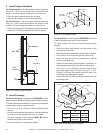
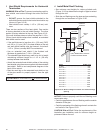
B. IntelliFire Plus™ Ignition System Wiring
• Wire the appliance junction cord to 220-240 VAC for
proper operation of the appliance.
WARNING!RiskofShockorExplosion!DONOT wire
IPI controlled appliance junction cord to a switched cir-
cuit. Incorrect wiring will override IPI safety lockout.
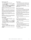
• Refer to Figure 12.1, IntelliFire Plus™ Pilot Ignition (IPI)
Wiring Diagram.
• This appliance is equipped with an IntelliFire Plus™
control valve which operates on a 6 volt system.
• For units installed in Australia, the residence’s 220/240
wall outlet to which this appliance’s power cord is con-
nected, must be wired to an in-line on/off switch. This is
required for servicing and/or resetting the control module
in the event of a control module LOCK-OUT.
• Plug the 6-volt AC power supply into the appliance junction
cord to supply power to the unit.
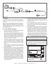
Figure 12.1 IPI Wiring Diagram /RC300AU
GREEN
(MAIN)
ORANGE
(PILOT)
8K1 WIRE
HARNESS
GROUND
CONTROL MODULE
DC REGULATOR
OPTIONAL ON/OFF
WALL SWITCH
RED
BLACK
WHITE
ORANGE
BATTERY PACK
6V DC (C X 4)
BROWN
TO OPTIONAL
COMPONENTS
TO JUNCTION
BOX 220-240 VAC
AUX300CE MODULE
240V FAN
FAN
AUX 1
AUX 2
S
I
GAS TUBE
FLAME
SENSE
6V DC SUPPLY
JUNCTION CORD
IGNITOR
C. Optional Accessories Requirements
• This appliance may be used with a wall switch, wall
mounted thermostat and/or a remote control.
Wiring for optional Hearth & Home Technologies approved
accessories should be done now to avoid reconstruction.
Follow instructions that come with those accessories.
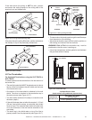
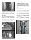
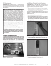
Optional Remote Control Receiver Location
The control module and remote control receiver can be
accessed through the air space below the rebox front
and the lower access door.
The IPI control module and the remote control receiver
are placed on the rebox bottom.
WARNING!RiskofShock!Label all wires prior to dis-
connection when servicing controls. Wiring errors can
cause improper and dangerous operation. Verify proper
operation after servicing.
WARNING!RiskofShock!Replace damaged wire with
type 105º C rated wire. Wire must have high temperature
insulation.