


Heat & Glo • 550TRSI-AUF, 550TRSILP-AUF • 2079-980 Rev. N • 5/12
50
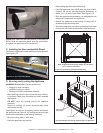
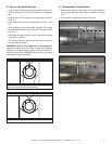
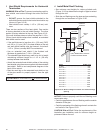
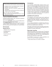
J. Install Metal Roof Flashing
• See minimum vent heights for various pitched roofs
(Figure 10.19) to determine the length of pipe to extend
through the roof.
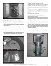
• Slide the roof ashing over the pipe sections extending
through the roof as shown in Figure 10.20.
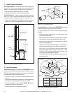
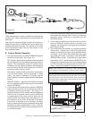
Figure 10.19 Minimum Height From Roof To Lowest Discharge
Opening
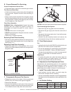
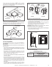
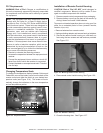
NOTICE:Failure to properly caulk the roof ashing could
cause water entry.
• Caulk the gap between the roof ashing and the outside
diameter of the pipe.
• Caulk the perimeter of the ashing where it contacts the
roof surface. See Figure 10.20.
CAUTION!RiskofFire!Follow the requirements of the
Australian gas installation code for minimum height re-
quirements above the roof.
H (MIN.) - MINIMUM HEIGHT FROM ROOF
TO LOWEST DISCHARGE OPENING
VERTICAL
WALL
TERMINATION
CAP
HORIZONTAL
OVERHANG
305 mm
X
ROOF PITCH
IS X/ 305 mm
LOWEST
DISCHARGE
OPENING
510 mm MIN.
610 mm MIN.
Angle H (Min.) mm
0°-26.6° .......................................................... 500*
26.6°-30.3° .......................................................... 500*
30.3°-33.7° .......................................................... 500*
33.7°-36.9° .......................................................... 610*
36.9°-39.8° .......................................................... 760
39.8°-42.5° .......................................................... 990
42.5°-45.0° ........................................................1 220
45.0°-49.4° ........................................................1 520
49.4°-53.1° ........................................................1 830
53.1°-56.3° ........................................................2 130
56.3°-59.0° ........................................................2 290
59.0°-60.3° ........................................................2 440
Important Notice: Heat shields may not be eld constructed.
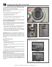
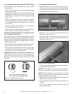
I. Heat Shield Requirements for Horizontal
Termination
WARNING!RiskofFire!To prevent overheating and re,
heat shields must extend through the entire wall thick-
ness.
• DO NOT remove the heat shields attached to the
wall shield restop and the horizontal termination cap
(shown in Figure 10.18).
• Heat shields must overlap 1-1/2 in. (38 mm) mini-
mum.
There are two sections of the heat shield. One section
is factory-attached to the wall shield restop. The other
section is factory-attached to the cap. See Figure 10.18.
If the wall thickness does not allow the required 1-1/2 in.
(38 mm) heat shield overlap when installed, an extended
heat shield must be used.
• If the wall thickness is less than 4 in. (102 mm) (DVP)
or 4-3/8 in. (111 mm) (SLP), the heat shields on the cap
and wall shield restop must be trimmed. A minimum
1-1/2 in. (38 mm) overlap MUST be maintained.
• Use an extended heat shield if the nished wall
thickness is greater than 7-1/4 in. (184 mm).
• The extended heat shield may need to be cut to length
maintaining sufcient length for a 1-1/2 in. (38 mm)
overlap between heat shields.
• Attach the extended heat shield to either of the existing
heat shields using the screws supplied with the extended
heat shield. Refer to vent components diagrams in the
back of this manual.
• Rest the small leg on the extended heat shield on top
of the pipe section to properly space it from the pipe
section.