


31
Heat & Glo • 550TRSI-AUF, 550TRSILP-AUF • 2079-980 Rev. N • 5/12
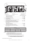
MODEL
550TRSI-AUF
550TRSILP-AUF
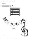
FLUE TERMINATION APPROVALS
DVP-TRAP2 HORIZONTAL TERMINATION CAP
DVP-FBHT HORIZONTAL TERMINATION CAP
DVP-TVHW VERTICAL TERMINATION CAP
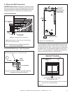
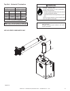
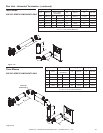
Flue System Approvals And Installations
These models have ue starting collars on both the top
and the back of the unit. Depending upon the installation,
decide which ONE set of starting collars will be used to at-
tach the ue system. The starting collar sealing cap must
remain on the starting collar NOT used.
These models use DVP and SLP series direct ue com-
ponents when using the TOP ue collars and DVP-series
direct ue components when using the REAR ue collars.
Approved ue system components are labeled for identi-
cation. NO OTHER FLUEING SYSTEMS OR COMPO-
NENTS MAY BE USED. Detailed installation instructions
are included with each ue termination kit and should be
used in conjunction with this manual. Figure 7.9 shows
ue system components and terminations.
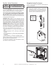
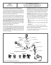
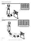
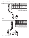
Identifying Flue Components
The ue systems installed on this gas heater may include
one, two, or three 90°
elbow assemblies. The relationships
of vertical rise to horizontal run in ue congurations using
90° elbows MUST BE strictly adhered to. The rise to run
relationships are shown in the ueing drawings and tables
on the next few pages.
WARNING!RiskofFire!This gas appliance and ue as-
sembly must ue directly to the outside and must never
be attached to a chimney serving a separate solid fuel
burning appliance. Each gas appliance must use a sepa-
rate ue system-common ue systems are prohibited.
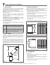
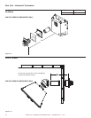
WARNING! Risk of Fire! DO NOT apply combustible
materials beyond the minimum clearances. Comply with
all minimum clearances to combustibles as specied in
this manual. Overlapping material could ignite and will in-
terfere with proper operation of doors and louvers.
• Horizontal sections 3 in. (76 mm) from the top of the
pipe.
• Horizontal sections 2-1/2 in. (64 mm) at wall shield
restops.
• Horizontal sections 1 in. (25 mm) from sides and bottom
of the pipe.
• Vertical sections 1 in. (25 mm) on all sides of pipe.
Failure to keep insulation or other material away from vent
pipe may cause over heating and re.
For alternative installations, other than depicted, contact
your dealer for further information.
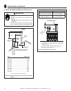
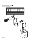
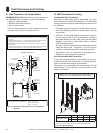
Figure 7.9 Flue Components and Terminations
HORIZONTAL
TERMINATION
WALL FIRESTOP
90 DEGREE
ELBOW
VERTICAL
TERMINATION
STORM COLLAR
ROOF FLASHING
HORIZONTAL PIPE
SUPPORT
PIPE LENGTH
WALL BRACKET
CEILING
FIRESTOP
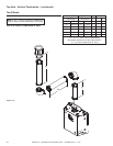
DVP-SERIES
SLP-TVHW
SLP-TRAP2
SLP SERIES
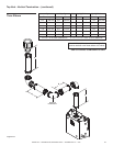
DVP-TRAP2
DVP-TVHW
Flue system termination kits
DVP-FBHT